
User's Manual

d) Automatic stop upon reaching end of operating distance
e receiver can also move to standby automatically when the transmitter is used outside
of safe operating distance.
c) Time release
For safety reasons the receiver also moves to standby mode when more than 5 minutes
have elapsed between signals from transmitter to receiver.
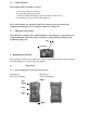
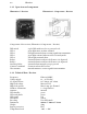
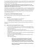
2.2.7 Allocation fop Terminals
ere is a six pole connection terminal in the receiver box at the bottom right.
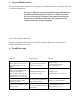
Illustration 7: Illustration 8:
Connection terminal Photo of Receiver
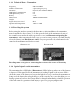
Map of Terminals
Terminal 1 Output switching relay 1
Terminal 2 Output switching relay 2
Terminal 3 Ground
Terminal 4 open contact start/stop relay
Terminal 5 +12 – 24 V DC power supply
Terminal 6 Output switching relay 3 (optional)
3. Tips for Connector Allocation and start up
Mounting, setting up and maintenance of the system is only to be done by schooled
professionals. Furthermore, connecting the wireless unit to the machine being controlled
can only be done by a recognized expert in the type of machines being used.
– All work on the piece of machinery or on the receiver must be done with no
electricity connected.
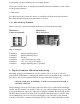
e mounting position chosen for the receiver should be easy to reach and not inside the
vehicle. Also the receiver box should be able to be seen easily for diagnostic purposes. is
position should not be exposed to either direct sunlight or rainfall. e mounting surface
should be at to prevent contortion of the box which could allow water to enter the unit.
e mounting holes can be accessed by removing the cover. e cables going outward
from the box should be orientated downwards. Use the cable connections delivered with