
User's Manual

2.2 Receiver
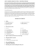
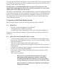
2.2.1 Open view and components
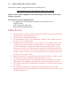
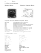
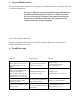
Illustration 5: Receiver Illustration 6: Components – Receiver
Components of the receiver (Illustration 6 Components – Receiver)
DIP switch 8 pole DIP switch used to set personal code
LED 1 green light turns on when activated
LED 2 red light activated when receiving signal from transmitter
LED 3 green light activated when receiver is in ready mode
LED 4 yellow light activated when
Relay 1 activated when in ready mode if button 1 is depressed
Relay 2 activated when in ready mode if button 2 is depressed
Start/Stop Relay activated when emergency stop is pressed
Connector terminal Connection from the receiver
Wire antenna internal antenna to receive signal from transmitter
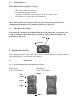
2.2.2 Technical Data - Receiver
Frequency FM 914.5 MHZ
Voltage supply 12 – 24 Volt DC
No signal current 12V 25mA, 24V 35mA
High load voltage Max. 24V DC
High load current Max. 5 amp pro Channel
Number of Functions 2 + Stop function
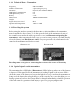
Antenna internal
LED Standby green
LED ready mode green
LED signal red
LED mode yellow
Encoding 8 bit DIP switch
Dimension 100mm X 100mm X 60mm
Weight 350g
Ingress protection IP65
Temperature levels -20C - + 50C