
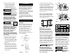
Installation Guide

∆ Not Shown
Reference
Number Description Part Number Qty
1 Motor, 0.75 HP, 3450 RPM, TEFC 90-40289 1
Motor, 1 HP, 3450 RPM, TEFC 90-40288 1
2 Hex washer head screw, self-tapping, 1/4-20 X 5/8 90-23039-10 7
3 Motor adaptor, AC motor 90-32452 1
4 Lockwasher, 3/8 92-23057-01 4
5 Hex head cap screw, 3/8-16 x 3/4 92-23036-01 4
6 Socket head cap screw, 1/4-20 x 3/4 90-23055-06 4
7 Wind direction label 92-10211 1
8 Outboard drum support 90-32262 1
10 Drum bearing 90-12575 2
11 Drag button spring 90-23152-08 1
12 Drag button 90-22612 1
13 Coupling assembly, AC Winch 90-22355 1
14 Square key, 3/16 x 1 90-23042-05 1
15 Thrust washer, .030 oil finish 90-23120-08 1
16 Brake assembly 90-25036 1
17 Not applicable this model ——
18 Not applicable this model ——
19 Not applicable this model ——
20 Not applicable this model ——
21 Not applicable this model ——
22 Not applicable this model ——
23 Tie rod, 7” 90-20008-02 2
24 Drum assembly, AC Winch 90-31069-05 1
25 Set screw, M8 x 10 94-23164-09 1
26 Thrust washer 90-12574 1
27 Inboard drum support 90-32199 1
29 Square nut, 3/8-16 90-23084-04 4
30 Clevis hook assembly 90-20435 1
31 Wire rope assembly, 5/16” x 100’ 1580 1
32 Baseplate, AC Winch 90-32364 1
33 Hex socket flat head screw, 3/8-16 x 7/8 90-23056-09 4
34 Drum driving plate 90-22183-01 1
35 Rotating ring gear, 66T, HT 90-32232-01 1
36 Ring gear bearing and separator 90-22607 1
37 Carrier bushing 90-10417 1
38 Drive shaft assembly, AC 90-24498 1
39 Carrier assembly, 253:1 90-32238 1
40 Gearbox bushing 90-10418 1
41 Stationary ring gear, 63T, HT 90-32233-01 1
42 •Locking pin, X9, plated 90-22113-01 1
43 •Clutch spring 90-23152-07 1
44 Product/Warning label, 1723 90-22508-01 1
Product/Warning label, 1730000 90-24490 1
45 •Lever 90-31028 1
46 •Spring pin, 3/32 x 5/8 90-23017-09 1
47 •Dust cover 90-22103 1
48 •Cap plug 90-23171-07 1
49 •Gearbox casting, machined 90-40054 1
51 •Push-on retaining ring 90-23213-04 2
∆ Grease (for one relube) 90-15020 1
∆ Drum switch 1796 1
∆ Handsaver 89-32300 1
• Available as: Gearbox Housing Assembly 90-20080 1
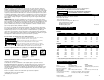
REPLACEMENT
PARTS LIST
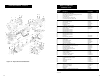
Figure 11 – Repacement Parts Illustration
6
2
4
3
5
7
8
10
11
12
13
14
16
15
23
24
25
26
27
6
29
31
30
32
33
34
35
36
37
38
39
40
41
44
43
42
45
46
47
48
49
51
1
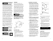
NOTE GROOVE
ORIENTATION
10
2
REPLACEMENT PARTS
13
12