
User manual


Installing the device
20
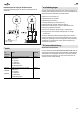
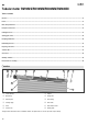
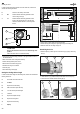
In order to determine bearing position P in the roller shutter box, measure and
calculate the following dimensions:
D Diameter of the rolled up roller shutter
X D/2 Distance between the bearing position P and the
centre of the guide rail (3)
Y >X Distance between the bearing position P and the
bottom of the roller shutter box. So that the roller
shutter has sufficient clearance, Y must be greater
than X.
D
X
Y
1
2
3
P
ATTENTION
Damage to the tubular motor due to the roller shutter being rolled
up slanted.
¾ Make sure that the device is installed horizontally.
¾ Using a pencil, mark the bearing positions P on the right and left inner sides of
the roller shutter box.
¾ Make sure that the marks are aligned horizontally.
¾ Hold the bearings centrally on the marks.
¾ Mark the holes to be drilled using a pencil.
¾ Drill the holes using an 8 mm drill bit.
¾ Insert the plugs.
¾ Screw the bearings down tightly.
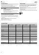
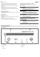
Sawing the winding shaft to length
In order to determine the length L of the winding shaft, measure and calculate the
following dimensions:
A Clear width of the roller shutter box
B b1+b2+b3
b1 Depth of the counter bearing
b2 Width of the roller capsule limit stop
b3 1/3 of the roller capsule shaft length
C c1+c2+c3
c1 Depth of the adapter limit stop
c2 Depth of the driving head
c3 Depth of the drive bearing
L A-(B+C)
L
B
C
A
b1 c1 c2 c3b2
b3
BC
¾ Using a pencil, mark the length L on the winding shaft.
¾ Saw the winding shaft to length at a right angle using a metal cutting saw.
¾ Deburr the inner and outer edges using a file.
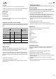
Assembling the device
¾ Slide the adapter (1) with the groove over the limit ring (2) spring on the driving
head (3).
1 2 3
¾ 1. Slide the driver (1) up to the limit stop onto the tubular motor's axle pin (2).
¾ 2. Secure the driver with the enclosed securing clip (3).
1
1. 2.
2
3