
User`s manual


Chapter 2: Installation
2-41
IPMI LAN
A
JOH1
JPS2
JPS3
JPS1
JI2C2
J21
JWD1
JPTG1
JP6
JP7
JPL1
JPG1
JPB1
JPW1
JPW2
JPW3
I-SATA5
I-SATA3
I-SATA1
JS3
LED1
SFP2
SFP1
JTPM1
JIPMB1
JSD1
COM2
JSTBY1
SP1
JBT1
USB2/3
T-SGPIO1
T-SGPIO2
FANA
FAN5
P1-DIMMC1
P1-DIMMC2
P1-DIMMC3
SXB1C
CPU2_PORT2
SXB1B
SXB1A
P1-DIMMD1
BATTERY
CPU1_PORT3
P1-DIMMD2
P2-DIMME1
CPU2_PORT3A/3B
SXB2
UID
P1-DIMMD3
Slot1 PCI-E 3.0 x16
LAN4
FAN4
P2-DIMME2
P2-DIMME3
P2-DIMMF1
LAN3
P2-DIMMF2
P2-DIMMF3
LAN2
FAN3
CPU1
CPU2
LAN1
FAN2
P1-DIMMB3
P1-DIMMB2
BUZZER
COM1
VGA1
P1-DIMMB1
P2-DIMMH3
P1-DIMMA3
P2-DIMMH2
P2-DIMMH1
P1-DIMMA2
P2-DIMMG3
USB0/1
IPMI_LAN
FAN1
P1-DIMMA1
P2-DIMMG2
P2-DIMMG1
PWR_I2C
KB/MOUSE
I-SATA4 I-SATA2 I-SATA0
LEM2
LE2
USB6
USB4/5
JL1
JF1
SAS4-7 SAS0-3
LEDS1
LEDS2
FPCTRL
CPU1 Slot2 PCI-E 3.0 x16 + X16
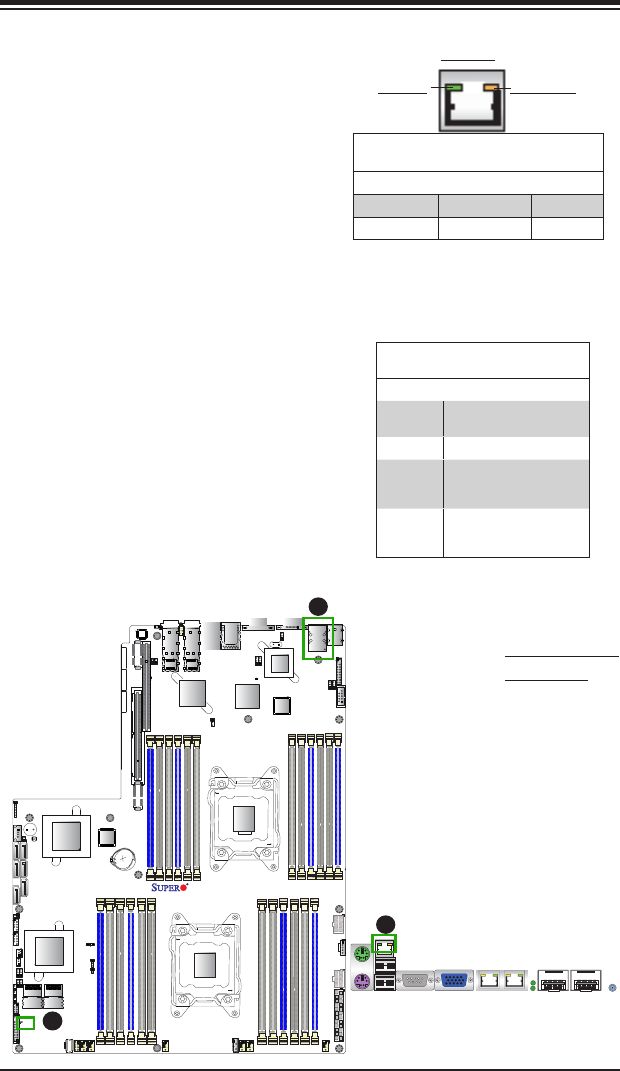
X9DRW-7TPF+
Rev. 1.01
LSI 2208
SAS CTRL
Inel LAN
CTRL
Inel LAN
CTRL
Nuvoton
BMC
Inel PCH
CLOSE 1st
OPEN 1st
CLOSE 1st
OPEN 1st
JI2C1
LE1
JPME2
JPME1
10G MAC CODE
10G SAN MAC
1G MAC CODE
JPI2C1
Onboard Power LED
An Onboard Power LED is located at LE1
on the motherboard. When this LED is on,
the system is on. Be sure to turn off the
system and unplug the power cord before
removing or installing components. See
the table on the right for more information.
Onboard PWR LED Indicator (LE1)
LED Settings
LED Color Status
Off System Off (PWR cable
not connected)
Green System On
Green:
Flashing
Quickly
ACPI S1 State
Green:
Flashing
Slowly
ACPI S3 (STR) State
A. IPMI LAN LEDs
B. PWR LED
A
B
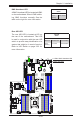
IPMI-Dedicated LAN LEDs
In addition to the GLAN and 10G_LAN Eth-
ernet ports, an IPMI-Dedicated LAN is also
located above the Backplane USB ports 0/1
on the motherboard. The amber LED on
the right indicates activity, while the green
LED on the left indicates the speed of the
connection. See the table on the right for
more information.
Link LED Activity LED
IPMI LAN Link LED (Left) &
Activity LED (Right)
Color/State Denition
Link (Left) Green: Solid 100 Mbps
Activity (Right) Amber: Blinking Active