
User`s manual


Chapter 2: Installation
2-35
JOH1
JPS2
JPS3
JPS1
JI2C2
J21
JWD1
JPTG1
JP6
JP7
JPL1
JPG1
JPB1
JPW1
JPW2
JPW3
I-SATA5
I-SATA3
I-SATA1
JS3
LED1
SFP2
SFP1
JTPM1
JIPMB1
JSD1
COM2
JSTBY1
SP1
JBT1
USB2/3
T-SGPIO1
T-SGPIO2
FANA
FAN5
P1-DIMMC1
P1-DIMMC2
P1-DIMMC3
SXB1C
CPU2_PORT2
SXB1B
SXB1A
P1-DIMMD1
BATTERY
CPU1_PORT3
P1-DIMMD2
P2-DIMME1
CPU2_PORT3A/3B
SXB2
UID
P1-DIMMD3
Slot1 PCI-E 3.0 x16
LAN4
FAN4
P2-DIMME2
P2-DIMME3
P2-DIMMF1
LAN3
P2-DIMMF2
P2-DIMMF3
LAN2
FAN3
CPU1
CPU2
LAN1
FAN2
P1-DIMMB3
P1-DIMMB2
BUZZER
COM1
VGA1
P1-DIMMB1
P2-DIMMH3
P1-DIMMA3
P2-DIMMH2
P2-DIMMH1
P1-DIMMA2
P2-DIMMG3
USB0/1
IPMI_LAN
FAN1
P1-DIMMA1
P2-DIMMG2
P2-DIMMG1
PWR_I2C
KB/MOUSE
I-SATA4 I-SATA2 I-SATA0
LEM2
LE2
USB6
USB4/5
JL1
JF1
SAS4-7 SAS0-3
LEDS1
LEDS2
FPCTRL
CPU1 Slot2 PCI-E 3.0 x16 + X16
X9DRW-7TPF+
Rev. 1.01
LSI 2208
SAS CTRL
Inel LAN
CTRL
Inel LAN
CTRL
Nuvoton
BMC
Inel PCH
CLOSE 1st
OPEN 1st
CLOSE 1st
OPEN 1st
JI2C1
LE1
JPME2
JPME1
10G MAC CODE
10G SAN MAC
1G MAC CODE
JPI2C1
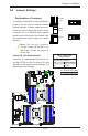
2-8 Jumper Settings
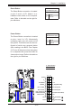
Explanation of Jumpers
To modify the operation of the motherboard,
jumpers can be used to choose between
optional settings. Jumpers create shorts be-
tween two pins to change the function of the
connector. Pin 1 is identied with a square
solder pad on the printed circuit board. See
the motherboard layout pages for jumper
locations.
Note: On two-pin jumpers,
"Closed" means the jumper is on
and "Open" means the jumper is
off the pins.
Connector
Pins
Jumper
Cap
Setting
Pin 1-2 short
3 2 1
3 2 1
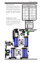
GLAN/10G_LAN Enable/Disable
Use JPL1 to enable/disable LAN Ports 1/2,
and use JPTG1 for 10G_LAN Ports 3/4. See
the table on the right for jumper settings. The
default setting is Enabled.
LAN1/2, LAN3/4 Enable
Jumper Settings
Jumper Setting Denition
1-2 Enabled (default)
2-3 Disabled
A. LAN Ports 1/2 Enable
B. LAN Ports 3/4 Enable
A
B