X8DAH+ X8DAH+-F X8DAH+-LR X8DAH+-F-LR USER’S MANUAL Revision 1.
The information in this User’s Manual has been carefully reviewed and is believed to be accurate. The vendor assumes no responsibility for any inaccuracies that may be contained in this document, makes no commitment to update or to keep current the information in this manual, or to notify any person or organization of the updates. Please Note: For the most up-to-date version of this manual, please see our website at www.supermicro.com. Super Micro Computer, Inc.
Preface Preface About this Manual This manual is written for system integrators, PC technicians and knowledgeable PC users. It provides information for the installation and use of the X8DAH+/ X8DAH+-F/X8DAH+(-F)-LR motherboard.
X8DAH+/X8DAH+-F/X8DAH+(-F)-LR User's Manual Conventions Used in the Manual Special attention should be given to the following symbols for proper installation and to prevent damage done to the components or injury to yourself. Danger/Caution: Instructions to be strictly followed to prevent catastrophic system failure or to avoid bodily injury. Warning: Important information given to ensure proper system installation or to prevent damage to the components.
Contacting Supermicro Contacting Supermicro Headquarters Address: Super Micro Computer, Inc. 980 Rock Ave. San Jose, CA 95131 U.S.A. Tel: +1 (408) 503-8000 Fax: +1 (408) 503-8008 Email: marketing@supermicro.com (General Information) support@supermicro.com (Technical Support) Website: www.supermicro.com Europe Address: Super Micro Computer B.V. Het Sterrenbeeld 28, 5215 ML 's-Hertogenbosch, The Netherlands Tel: +31 (0) 73-6400390 Fax: +31 (0) 73-6416525 Email: sales@supermicro.
X8DAH+/X8DAH+-F/X8DAH+(-F)-LR User's Manual Table of Contents Preface............................................................................................................ 3 Chapter 1 Introduction .............................................................................1-1 1-1 Overview.......................................................................................................... 1-1 1-2 Chipset Overview.................................................................................
Table of Contents Power Fail LED......................................................................................... 2-23 Reset Button ............................................................................................ 2-24 Power Button ............................................................................................ 2-24 2-6 Connecting Cables......................................................................................... 2-25 Power Connectors .............................
X8DAH+/X8DAH+-F/X8DAH+(-F)-LR User's Manual Chapter 4 BIOS ..........................................................................................4-1 4-1 Introduction....................................................................................................... 4-1 Starting BIOS Setup Utility............................................................................... 4-1 How To Change the Configuration Data..........................................................
Chapter 1: Introduction Chapter 1 Introduction 1-1 Overview Checklist Congratulations on purchasing your computer motherboard from an acknowledged leader in the industry. Supermicro boards are designed with the utmost attention to detail to provide the highest standards in quality and performance. Check that the following items have all been included with your motherboard. If anything listed here is damaged or missing, contact your retailer. The following items are included in the retail box.
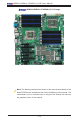
X8DAH+/X8DAH+-F/X8DAH+(-F)-LR User's Manual X8DAH+/X8DAH+-F/X8DAH+(-F)-LR Image Note: The drawings and pictures shown in this manual were based on the latest PCB Revision available at the time of publishing of the manual. The motherboard you’ve received may or may not look exactly the same as the graphics shown in the manual.
Chapter 1: Introduction X8DAH+/X8DAH+-F/X8DAH+(-F)-LR Layout JPI2C1 PWR I2C FAN7 CPU FAN1 FAN6 FAN5 P2 DIMM3A P2 DIMM3B JPW1 JPW2 JPW3 P2 DIMM3C CPU1 JF1 VGA (Top) P2 DIMM1A FAN2 P2 DIMM1B P2 DIMM1C ALWAYS POPULATE DIMM1 FIRST IPMI LAN COM1 (Bottom) FPCTL KB/MS P2 DIMM2B P2 DIMM2C PHY Chip USB 2/3/4/5 USB0/1 FAN1 P2 DIMM2A P1 DIMM1C JD1 LAN1 (Bottom) LAN2 (Top) P1 DIMM1B P1 DIMM1A CPU2 P1 DIMM2C AUDIO Header P1 DIMM2B CPU2 FAN P1 DIMM3B P1 DIMM3A Slot7 PCI-E 2.
X8DAH+/X8DAH+-F/X8DAH+(-F)-LR User's Manual Quick Reference JPI2C1 PWR I2C FAN7 CPU FAN1 FAN6 FAN5 P2 DIMM3A P2 DIMM3B JPW1 JPW2 JPW3 P2 DIMM3C CPU1 JF1 VGA (Top) P2 DIMM1A FAN2 P2 DIMM1B P2 DIMM1C ALWAYS POPULATE DIMM1 FIRST IPMI LAN COM1 (Bottom) FPCTL KB/MS P2 DIMM2B P2 DIMM2C PHY Chip USB 2/3/4/5 USB0/1 FAN1 P2 DIMM2A P1 DIMM1C JD1 LAN1 (Bottom) LAN2 (Top) P1 DIMM1B P1 DIMM1A CPU2 P1 DIMM2C AUDIO Header P1 DIMM2B CPU2 FAN P1 DIMM3B P1 DIMM3A Slot7 PCI-E 2.
Chapter 1: Introduction X8DAH+/X8DAH+-F/X8DAH+(-F)-LR Quick Reference Jumper Description Default Setting JBT1 CMOS Clear Open (Normal) JPIDE1 Compact Flash Enabled Closed (Enabled) JI2C1/JI2C2 SMB to PCI/PCI-E Slots Open/Open (Disabled) JPG1 VGA Enable Pins 1-2 (Enabled) (X8DAH+-F/(-LR) only) JPI1 1394-1/1394 Enable Pins 1-2 (Enabled) JPL1 LAN1/2 Enable Pins 1-2 (Enabled) JWD1 Watch Dog Pins 1-2 (Reset) Connector Description CNF1/CNF2 1394a-1/-2 Ports Audio Connections BP 7.
X8DAH+/X8DAH+-F/X8DAH+(-F)-LR User's Manual Motherboard Features CPU • Two Intel® 5500/5600 Series (LGA 1366) processors. Each processor supports two full-width Intel QuickPath Interconnect (QPI) @6.4 GT/s with a total of up to 51.2 GB/s Data Transfer Rate (6.4 GB/s per direction) (See Note 2 on P. 1-3.) Memory • RDIMM • 240-pin Reg. DDR3 ECC 1333/1066/800 MHz memory with support of up to 288 GB in 18 slots Note 1. 240-pin Dual Rank (DR) 16 GB Reg.
Chapter 1: Introduction Expansion Slots • • • • Three PCI-E 2.0 x8 slots (Slot 1/Slot 3/Slot7) Two PCI-E 2.0 x16 slots (Slot 2/Slot 6) One PCI-E 2.0 x4 (in x8) slots (Slot 5) One PCI-E 2.0 x8 (in x16) slots (Slot 4) BIOS • • 32 Mb AMI SPI Flash ROM PCI 2.2, ACPI 1.0/2.0/3.0, Plug and Play (PnP), DMI 2.3, USB Keyboard support, and SMBIOS 2.3 PC Health Monitoring • Onboard voltage monitors for CPU0 Vcore, CPU1 Vcore, 1.5V, 5V, 5VSB, 12V, -12V, 3.3Vcc, 3.
X8DAH+/X8DAH+-F/X8DAH+(-F)-LR User's Manual • A PHY chip supports the Dedicated IPMI LAN (X8DAH+-F/(-LR) only) (Note 2) • One VGA Port supported by the Winbond WPCM 450R BMC Controller (X8DAH+-F/(-LR) only) • • PS/2 mouse/keyboard ports, one COM port and one Serial header • • Super I/O: Winbond W83627DHG • • Two Internal1394 headers • IPMI 2.0 with full KVM support (X8DAH+-F/(-LR) only) (Note 2) Up to ten USB 2.
Chapter 1: Introduction Notes 1-9
X8DAH+/X8DAH+-F/X8DAH+(-F)-LR User's Manual X8DAH+ System Diagram CPU2 QPI SLOT#2 PCI-E X16 QPI QPI Ports 3~6 (IOH 36D) Ports 7~10 Audio CTRL HD Intel ICH1OR SPI LPC BUS FLOPPY BIOS USB2.
Chapter 1: Introduction X8DAH+-F/(-LR) System Diagram CPU2 QPI SLOT#2 PCI-E X16 QPI QPI Ports 3~6 (IOH 36D) Ports 7~10 Audio CTRL HD Intel ICH1OR SPI PCI 33MHZ RMII 3rd LAN RMII LPC BUS BMC WPCM450 DDR II VGA FLOPPY USB AUDIO BIOS USB2.
X8DAH+/X8DAH+-F/X8DAH+(-F)-LR User's Manual 1-2 Chipset Overview Built upon the functionality and the capability of the 5500/5600 Series Processor platform, the X8DAH+/X8DAH+-F/X8DAH+(-F)-LR motherboard provides the performance and feature set required for dual-processor/IOH-based high-end systems optimized for High Performance Computing (HPC)/Cluster platforms. The 5520 chipset consists of the IOH 36D (I/O Hub), and the ICH10R (South Bridge).
Chapter 1: Introduction 1-3 Special Features Recovery from AC Power Loss BIOS provides a setting for you to determine how the system will respond when AC power is lost and then restored to the system. You can choose for the system to remain powered off (in which case you must hit the power switch to turn it back on) or for it to automatically return to a power- on state. See the Advanced BIOS Setup section to change this setting. The default setting is Last State.
X8DAH+/X8DAH+-F/X8DAH+(-F)-LR User's Manual System Resource Alert This feature is available when used with Supero Doctor III in the Windows OS environment or used with Supero Doctor II in Linux. Supero Doctor is used to notify the user of certain system events. For example, you can also configure Supero Doctor to provide you with warnings when the system temperature, CPU temperatures, voltages and fan speeds go beyond a pre-defined range.
Chapter 1: Introduction 1-6 Power Supply As with all computer products, a stable power source is necessary for proper and reliable operation. It is even more important for processors that have high CPU clock rates. The X8DAH+/X8DAH+-F/X8DAH+(-F)-LR can accommodate 24-pin ATX power supplies. Although most power supplies generally meet the specifications required by the CPU, some are inadequate.
X8DAH+/X8DAH+-F/X8DAH+(-F)-LR User's Manual ment through an SMI or SCI function pin. It also features auto power management to reduce power consumption. 1-8 Overview of Winbond WPCM450 Controller (For X8DAH+-F/(-LR) Only) The Winbond WPCM450 Controller is a Baseboard Management Controller (BMC) that supports the 2D/VGA-compatible Graphics Cores, Virtual Media, and Keyboard/ Video/Mouse Redirection (KVMR) modules.
Chapter 2: Installation Chapter 2 Installation 2-1 Static-Sensitive Devices Electrostatic Discharge (ESD) can damage electronic components. To prevent damage to your system board, it is important to handle it very carefully. The following measures are generally sufficient to protect your equipment from ESD. • • • • • • • Precautions Use a grounded wrist strap designed to prevent static discharge. Touch a grounded metal object before removing the board from the antistatic bag.
X8DAH+/X8DAH+-F/X8DAH+(-F)-LR User's Manual 2-2 Motherboard Installation All motherboards have standard mounting holes to fit different types of chassis. Make sure that the locations of all the mounting holes for both motherboard and chassis match. Although a chassis may have both plastic and metal mounting fasteners, metal ones are highly recommended because they ground the motherboard to the chassis. Make sure that the metal standoffs click in or are screwed in tightly.
Chapter 2: Installation 2-3 Processor and Heatsink Installation ! When handling the processor package, avoid placing direct pressure on the label area of the fan. Notes: 1. Always connect the power cord last and always remove it before adding, removing or changing any hardware components. Make sure that you install the processor into the CPU socket before you install the CPU heatsink. 2. Make sure to install the motherboard into the chassis before you install the CPU heatsink and heatsink fans. 3.
X8DAH+/X8DAH+-F/X8DAH+(-F)-LR User's Manual CPU Socket CPU 4. After removing the plastic cap, using your thumb and the index finger, hold the CPU at the north and south center edges. Socket Keys 5. Align the CPU key, the semicircle cutout, against the socket key, the notch below the gold color dot on the side of the socket. 6. Once both the CPU and the socket are aligned, carefully lower the CPU straight down into the socket.
Chapter 2: Installation Installing a CPU Heatsink 1. Do not apply any thermal grease to the heatsink or the CPU die because the required amount has already been applied. Screw#1 Screw#2 2. Place the heatsink on top of the CPU so that the four mounting holes are aligned with those on the retention mechanism. Screw#1 Install Screw#1 3. Install two diagonal screws (ie the #1 and the #2 screws) and tighten them until just snug (-do not fully tighten the screws to avoid possible damage to the CPU.) 4.
X8DAH+/X8DAH+-F/X8DAH+(-F)-LR User's Manual Removing the Heatsink Warning: We do not recommend that the CPU or the heatsink be removed. However, if you do need to remove the heatsink, please follow the instructions below to uninstall the heatsink and prevent damage to the CPU or other components. 1. Unplug the power cord from the power supply. 2. Disconnect the heatsink fan wires from the CPU fan header. 3.
Chapter 2: Installation 2-4 Memory Installation Note: Check the Supermicro website for recommended memory modules. CAUTION Exercise extreme care when installing or removing DIMM modules to prevent any possible damage. Also note that the memory is interleaved to improve performance (See step 1). Press down the release tabs DIMM Installation 1. Insert the desired number of DIMMs into the memory slots, starting with DIMM #P1-DIMM1A.
X8DAH+/X8DAH+-F/X8DAH+(-F)-LR User's Manual Memory Support • RDIMM • 240-pin Reg. DDR3 ECC 1333/1066/800 MHz memory with support of up to 288 GB in 18 slots Note 1. 240-pin Dual Rank (DR) 16 GB Reg. ECC DDR3 1333/1066/800 MHz memory will support up to 288 GB. Memory speed will be downgraded to 800 MHz. (Refer to the notes in the following memory configuration tables.) Note 2. 240-pin Quad Rank (QR) 16 GB Reg. ECC DDR3 1066/800 MHz memory will support up to 192 GB (with 6 DIMMs max. per CPU).
Chapter 2: Installation DIMM Module Population Configuration 1. For motherboards prior to PCB Rev. 2.0 For memory to work properly, follow the tables below for memory installation: Memory Population for Optimal Performance for Boards Prior to PCB Rev. 2.
X8DAH+/X8DAH+-F/X8DAH+(-F)-LR User's Manual 2. For PCB Rev. 2.0 or Newer Boards For memory to work properly, follow the tables below for memory installation: Memory Population for Optimal Performance for PCB Rev. 2.
Chapter 2: Installation RDIMM Population for the Motherboard w/5500 Processors Installed DIMM Slots per Channel DIMMs Populated per Channel DIMM Type (Reg.= Registered) Speeds (in MHz) Ranks per DIMM (any combination; SR=Single Rank, DR=Dual Rank, QR=Quad Rank) 3 1 Reg. DDR3 ECC 800,1066,1333 SR or DR 3 1 Reg. DDR3 ECC 800,1066 QR 3 2 Reg. DDR3 ECC 800,1066 Mixing SR, DR 3 2 Reg. DDR3 ECC 800 (Note) Mixing SR, DR, QR 3 3 Reg.
X8DAH+/X8DAH+-F/X8DAH+(-F)-LR User's Manual 1.5V UDIMM Population for the Motherboard w/5600 Processors Installed DIMM Slots per Channel DIMMs Populated per Channel DIMM Type (Unb.= Unbuffered) Speeds (in MHz) Ranks per DIMM (any combination; SR=Single Rank, DR=Dual Rank, QR=Quad Rank) 3 1 Unb. DDR3 ECC/Non-ECC 800,1066,1333 SR or DR 3 2 Unb.
Chapter 2: Installation Possible System Memory Allocation & Availability System Device Size Physical Memory Remaining (-Available) (4 GB Total System Memory) Firmware Hub flash memory (System BIOS) 1 MB 3.99 GB Local APIC 4 KB 3.99 GB Area Reserved for the chipset 2 MB 3.99 GB I/O APIC (4 Kbytes) 4 KB 3.99 GB PCI Enumeration Area 1 256 MB 3.76 GB PCI Express (256 MB) 256 MB 3.51 GB PCI Enumeration Area 2 (if needed) -Aligned on 256-MB boundary- 512 MB 3.01 GB VGA Memory 16 MB 2.
X8DAH+/X8DAH+-F/X8DAH+(-F)-LR User's Manual 2-5 Control Panel Connectors/IO Ports The I/O ports are color coded in conformance with the PC 99 specification. See the picture below for the colors and locations of the various I/O ports. 1. Back Panel Connectors/IO Ports 11 2 10 4 7 3 6 13 16 19 12 15 X8DAH+ Rev. 2.01 1 5 9 8 Back Panel I/O Port Locations and Definitions Back Panel Connectors 1. Keyboard (Purple) 2. PS/2 Mouse (Green) 3. VGA (Blue) (X8DAH+-F/(-LR) only) 4.
Chapter 2: Installation ATX PS/2 Keyboard and PS/2 Mouse Ports PS/2 Keyboard/Mouse Pin Definitions The ATX PS/2 keyboard and PS/2 mouse are located next to the Back Panel COM Port1 and VGA port on the motherboard. See the table at right for pin definitions.
X8DAH+/X8DAH+-F/X8DAH+(-F)-LR User's Manual Serial Ports Two COM connections (COM1 & COM2) are located on the motherboard. COM1 is located on the Backplane IO panel. COM2 is located next to PCI-E Slot 1 to provide additional serial connection support. See the table on the right for pin definitions.
Chapter 2: Installation Universal Serial Bus (USB) Back Panel USB (USB 0/1, 2~5) Six Universal Serial Bus ports (USB 0/1, 2~5) are located on the I/O back panel. Additionally, four USB connections (USB 6/7, 8, 9) are on the motherboard to provide front chassis access. (Cables are not included). See the tables on the right for pin definitions.
X8DAH+/X8DAH+-F/X8DAH+(-F)-LR User's Manual Ethernet Ports Two Ethernet ports (LAN 1/LAN2) are located at on the IO backplane. In addition, a dedicated LAN is also located on the X8DAH+-F (/-LR) to provide KVM support for IPMI 2.0. All these ports accept RJ45 type cables. (Note: Please refer to the LED Indicator Section for LAN LED information.
Chapter 2: Installation (Back Panel) High Definition Audio (HD Audio) Conn# This motherboard features a 7.1+2 Channel High Definition Audio (HDA) codec that provides 10 DAC channels. The HD Audio connections simultaneously supports multiple-streaming 7.1 sound playback with 2 channels of independent stereo output through the front panel stereo out for front L&R, rear L&R, center and subwoofer speakers. Use the Advanced software included in the CD-ROM with your motherboard to enable this function.
X8DAH+/X8DAH+-F/X8DAH+(-F)-LR User's Manual 2. Front Control Panel JF1 contains header pins for various buttons and indicators that are normally located on a control panel at the front of the chassis. These connectors are designed specifically for use with Supermicro server chassis. See the figure below for the descriptions of the various control panel buttons and LED indicators. Refer to the following section for descriptions and pin definitions. JF1 Header Pins X8DAH+ Rev. 2.
Chapter 2: Installation 3. Front Control Panel Pin Definitions NMI Button NMI Button Pin Definitions (JF1) The non-maskable interrupt button header is located on pins 19 and 20 of JF1. Refer to the table on the right for pin definitions. Pin# Definition 19 Control 20 Ground Power LED Power LED Pin Definitions (JF1) The Power LED connection is located on pins 15 and 16 of JF1. Refer to the table on the right for pin definitions. Pin# Definition 15 +5V 16 Ground A. NMI B.
X8DAH+/X8DAH+-F/X8DAH+(-F)-LR User's Manual HDD LED HDD LED Pin Definitions (JF1) The HDD LED connection is located on pins 13 and 14 of JF1. Attach a cable here to indicate HDD activities. See the table on the right for pin definitions. Pin# Definition 13 +5V 14 HD Active NIC1/NIC2 LED Indicators The NIC (Network Interface Controller) LED connection for GLAN port 1 is located on pins 11 and 12 of JF1, and the LED connection for GLAN Port 2 is on Pins 9 and 10.
Chapter 2: Installation Overheat (OH)/Fan Fail LED OH/Fan Fail LED Pin Definitions (JF1) Connect an LED cable to the Front UID and OH/Fan Fail connections on pins 7 and 8 of JF1 to provide advanced warnings for chassis overheat/ fan failure. Refer to the table on the right for pin definitions.
X8DAH+/X8DAH+-F/X8DAH+(-F)-LR User's Manual Reset Button Reset Button Pin Definitions (JF1) The Reset Button connection is located on pins 3 and 4 of JF1. Attach it to a hardware reset switch on the computer case. Refer to the table on the right for pin definitions. Pin# Definition 3 Reset 4 Ground Power Button The Power Button connection is located on pins 1 and 2 of JF1. Momentarily contacting both pins will power on/off the system.
Chapter 2: Installation 2-6 Connecting Cables ATX Power 24-pin Connector Pin Definitions Pin# Definition Pin # Power Connectors 13 A 24-pin main power supply connector(JPW1) and two 8-pin CPU PWR connectors (JPW2/ JPW3) on the motherboard. These power connectors meet the SSI EPS 12V specification. In addition to the 24-pin ATX power connector, the 12V 8-pin CPU PWR connectors at JPW2/JPW3 must also be connected to your power supply. See the table on the right for pin definitions.
X8DAH+/X8DAH+-F/X8DAH+(-F)-LR User's Manual Fan Headers Fan Header Pin Definitions This motherboard has six chassis/system fan headers (Fan 1 to Fan6) and two CPU fans (CPU1 Fan/CPU2 Fan) on the motherboard. In addition, I-Fan 1 and I-Fan 2 are available on a R 2.0 or newer version motherboard for IOH36D cooling. The 4-pin fans headers are backward compatible with the traditional 3-pin fans.
Chapter 2: Installation Internal Speaker Internal Buzzer (SP1) Pin Definition The Internal Speaker, located at SP1, can be used to provide audible indications for various beep codes. See the table on the right for pin definitions. Refer to the layout below for the locations of the Internal Buzzer (SP1). Pin# Definitions Pin 1 Pos. (+) Beep In Pin 2 Neg.
X8DAH+/X8DAH+-F/X8DAH+(-F)-LR User's Manual IEEE 1394a Connection CNF1 Pin Definitions CNF1 and CNF2 provide the IEEE 1394a connections on the motherboard. See the tables on the right for pin definitions. Pin# Defin. Pin# Defin 1 PTPA0+ 2 PTPA0- 3 GND 4 GND 5 PTPB0+ 6 PTPB0- 7 PWR 1394a 8 PWR 1394a 10 ZX CNF2 Pin Definitions Pin# Defin.
Chapter 2: Installation System Management Bus SMB Header Pin Definitions A System Management Bus header is located at SUBUS1 on the motherboard. Connect the appropriate cable here to use the SMB connection on your system. Pin# Definition 1 Data 2 Ground 3 Clock 4 No Connection PWR SMB Pin Definitions Power SMB (I2C) Connector Power System Management Bus (I2C) Connector (JPI2C) monitors power supply, fan and system temperatures. See the table on the right for pin definitions.
X8DAH+/X8DAH+-F/X8DAH+(-F)-LR User's Manual 2-7 Jumper Settings Explanation of Jumpers Connector Pins To modify the operation of the motherboard, jumpers can be used to choose between optional settings. Jumpers create shorts between two pins to change the function of the connector. Pin 1 is identified with a square solder pad on the printed circuit board. See the motherboard layout pages for jumper locations.
Chapter 2: Installation CMOS Clear JBT1 is used to clear CMOS. Instead of pins, this "jumper" consists of contact pads to prevent the accidental clearing of CMOS. To clear CMOS, use a metal object such as a small screwdriver to touch both pads at the same time to short the connection. Always remove the AC power cord from the system before clearing CMOS. Note: For an ATX power supply, you must completely shut down the system, remove the AC power cord and then short JBT1 to clear CMOS.
X8DAH+/X8DAH+-F/X8DAH+(-F)-LR User's Manual I2C Bus to PCI-Exp. Slots I2C for PCI/PCI-E slots Jumper Settings Jumpers JI2C1 and JI2C2 allow you to connect the System Management Bus (I2C) to PCI and PCI-Express slots. These two jumpers are to be set at the same time. The default setting is Open to disable the connections. See the table on the right for jumper settings.
Chapter 2: Installation VGA Enable (X8DAH+-F/(-LR) Only) VGA Enable Jumper Settings Jumper JPG1 allows you to enable video connections on the motherboard. See the table on the right for jumper settings. Jumper Setting Enabled (Default) 2~3 Disabled 1394a-1/1394a-2 Enable 1394a Enable Jumper Settings Use Jumper JPI1 to enable the 1394a connections at CNF1(1394a-1)/CNF2 (1394a-2) on the motherboard. See the table on the right for jumper settings.
X8DAH+/X8DAH+-F/X8DAH+(-F)-LR User's Manual 2-8 Onboard LED Indicators GLAN LEDs Rear View (when facing the rear side of the chassis) LAN 1/LAN 2 Activity LED (Right) LED State FAN7 CPU FAN1 FAN5 FAN6 JPI2C1 PWR I2C P2 DIMM3B Status Definition Green Flashing Active LED Color Definition Off No Connection or 10 Mbps Green 100 Mbps Amber 1 Gbps IPMI LAN (X8DAH+-F/(-LR) JPW1 IPMI LAN Link LED (Left) & Activity LED (Right) Color JPW2 Status Green: Solid 100 Mbps Activity (Right) Amb
Chapter 2: Installation Onboard Power LED Onboard PWR LED (DP4) Settings An Onboard Power LED is located at DP4 on the motherboard. When this LED is lit, the system is on. Be sure to turn off the system and unplug the power cord before removing or installing components. See the tables at right for more information.
X8DAH+/X8DAH+-F/X8DAH+(-F)-LR User's Manual 2-9 Floppy Drive, Serial ATA and SAS Connections Note the following when connecting the floppy and hard disk drive cables: • The floppy disk drive cable has seven twisted wires. • A red mark on a wire typically designates the location of pin 1. • A single floppy disk drive ribbon cable has 34 wires and two connectors to provide for two floppy disk drives.
Chapter 2: Installation IDE Connector IDE Drive Connector Pin Definitions AN IDE Connector is located on the motherboard. This connector can be used for a Compact Flash card. To use a Compact Flash card on this connector, you will need to enable the jumper located at JPIDE1. See the table on the right for pin definitions.
X8DAH+/X8DAH+-F/X8DAH+(-F)-LR User's Manual Serial ATA Ports Serial ATA Pin Definitions There are Six Serial ATA Ports (ISATA0~I-SATA 5) located on the motherboard. These ports provide serial-link signal connections, which are faster than the connections of Parallel ATA. See the table on the right for pin definitions. JPI2C1 PWR I2C FAN7 CPU FAN1 FAN6 FAN5 P2 DIMM3A P2 DIMM3B JPW1 JPW2 Pin# Definition 1 Ground 2 TX_P 3 TX_N 4 Ground 5 RX_N 6 RX_P 7 Ground A.
Chapter 3: Troubleshooting Chapter 3 Troubleshooting 3-1 Troubleshooting Procedures Use the following procedures to troubleshoot your system. If you have followed all of the procedures below and still need assistance, refer to the ‘Technical Support Procedures’ and/or ‘Returning Merchandise for Service’ section(s) in this chapter. Note: Always disconnect the power cord before adding, changing or installing any hardware components. Before Power On 1.
X8DAH+/X8DAH+-F/X8DAH+(-F)-LR User's Manual No Video 1. If the power is on but you have no video, remove all the add-on cards and cables. 2. Use the speaker to determine if any beep codes exist. Refer to the Appendix for details on beep codes. Losing the System’s Setup Configuration 1. Make sure that you are using a high quality power supply. A poor quality power supply may cause the system to lose the CMOS setup information. Refer to Section 1-6 for details on recommended power supplies. 2.
Chapter 3: Troubleshooting 7. Please follow the instructions given in the DIMM Population Tables listed in Section 2-4 to install your memory modules. 3-2 Technical Support Procedures Before contacting Technical Support, please take the following steps. Also, please note that as a motherboard manufacturer, Supermicro does not sell directly to endusers, so it is best to first check with your distributor or reseller for troubleshooting services.
X8DAH+/X8DAH+-F/X8DAH+(-F)-LR User's Manual Page 1-6 for memory support.) It is strongly recommended that you do not mix memory modules of different speeds and sizes. Please follow all memory installation instructions given on Section 2-4 in Chapter 2. Question: How do I update my BIOS? Answer: It is recommended that you do not upgrade your BIOS if you are not experiencing any problems with your system. Updated BIOS files are located on our website at http://www.supermicro.com/support/bios/.
Chapter 4: AMI BIOS Chapter 4 BIOS 4-1 Introduction This chapter describes the AMI BIOS Setup Utility for the X8DAH+/X8DAH+-F/ X8DAH+(-F)-LR. The AMI ROM BIOS is stored in a Flash EEPROM and can be easily updated. This chapter describes the basic navigation of the AMI BIOS Setup Utility setup screens. Warning: For your system memory to work properly, be sure to use the correct BIOS ROM for your system. For the X8DAH+, use the X8DAH+ BIOS. For the X8DAH+-LR, use the X8DAH+-LR BIOS.
X8DAH+/X8DAH+-F/X8DAH+(-F)-LR User's Manual How To Change the Configuration Data The configuration data that determines the system parameters may be changed by entering the AMI BIOS Setup utility. This Setup utility can be accessed by pressing at the appropriate time during system boot. Starting the Setup Utility Normally, the only visible Power-On Self-Test (POST) routine is the memory test. As the memory is being tested, press the key to enter the main menu of the AMI BIOS Setup Utility.
Chapter 4: AMI BIOS System Overview: The following BIOS information will be displayed: System Time/System Date Use this option to change the system time and date. Highlight System Time or System Date using the arrow keys. Enter new values through the keyboard and press . Press the key to move between fields. The date must be entered in MM/DD/YY format. The time is entered in HH:MM:SS format. (Note: The time is in the 24-hour format. For example, 5:30 P.M. appears as 17:30:00.
X8DAH+/X8DAH+-F/X8DAH+(-F)-LR User's Manual 4-3 Advanced Setup Configurations Use the arrow keys to select Advanced Setup and press to access the submenu items. Boot Feature Quick Boot If Enabled, this option will skip certain tests during POST to reduce the time needed for system boot. The options are Enabled and Disabled. Quiet Boot Use this feature to select the bootup screen display between POST messages or the OEM logo. Select Disabled to display the POST messages.
Chapter 4: AMI BIOS Hit 'Del' Message Display Select Enabled to display "Press DEL to run Setup" during POST. The options are Enabled and Disabled. Interrupt 19 Capture Interrupt 19 is the software interrupt that handles boot disk functions. When this item is set to Enabled, the ROM BIOS of the host adaptors will "capture" Interrupt 19 at bootup and allow the drives that are attached to these host adaptors to function as bootable disks.
X8DAH+/X8DAH+-F/X8DAH+(-F)-LR User's Manual Processor and Clock Options This submenu allows the user to configure the Processor and Clock settings. CPU Ratio If set to Manual, this option allows the user to set the ratio between the CPU Core Clock and the FSB Frequency. The options are Auto and Manual. Note: if an invalid ratio is entered, the AMI BIOS will restore the setting to the previous state.
Chapter 4: AMI BIOS Intel® Virtualization Technology (Available when supported by the CPU) Select Enabled to use Intel Virtualization Technology which will allow one platform to run multiple operating systems and applications in independent partitions, creating multiple "virtual" systems in one physical computer. The options are Enabled and Disabled. Note: If there is any change to this setting, you will need to power off and restart the system for the change to take effect.
X8DAH+/X8DAH+-F/X8DAH+(-F)-LR User's Manual C1E Support Select Enabled to support Enhanced Halt State. C1E significantly reduces the CPU's power consumption by reducing the CPU's clock cycle and voltage during a "Halt State." The options are Disabled and Enabled. Intel® C-STATE Tech If enabled, C-State is set by the system automatically to either C2, C3 or C4 state. The options are Disabled and Enabled.
Chapter 4: AMI BIOS QPI Frequency This selects the desired QPI frequency. The options are Auto, 4.800 GT, 5.866GT, 6.400 GT. QPI L0s and L1 This feature allows QPI to use lower power settings. L0s and L1 are automatically selected by the motherboard. The options are Disabled and Enabled. Memory Frequency This feature allows the user to force DDR3 memory to run at a frequency different from what is specified. The available options are Auto, Force DDR-800, Force DDR-1066, Force DDR-1333, and Force SPD.
X8DAH+/X8DAH+-F/X8DAH+(-F)-LR User's Manual North Bridge Configuration This feature allows the user to configure the settings for the Intel North Bridge. Intel I/O AT This feature works with the Intel I/O AT (Acceleration Technology) to accelerate the performance of a TOE device, which is a specialized, dedicated processor installed on an add-on card or a network card to handle some or all packet processing of this add-on card.
Chapter 4: AMI BIOS South Bridge Configuration USB Functions Select Enabled to use onboard USB connections. The Options are: Disabled and Enabled. Legacy USB Support Select Enabled to use Legacy USB devices. If this item is set to Auto, Legacy USB support will be automatically enabled if a legacy USB device is installed on the motherboard, and vise versa. The settings are Disabled, Enabled and Auto.
X8DAH+/X8DAH+-F/X8DAH+(-F)-LR User's Manual IDE/SATA Configuration When this submenu is selected, the AMI BIOS automatically detects the presence of the IDE devices and displays the following items: SATA#1 Configuration Select Compatible to set SATA#1 to legacy compatibility mode. Select Enhanced to set SATA#1 to native SATA mode. The options are Disabled, Compatible and Enhanced. Configure SATA#1 as This feature is used to select the drive type for SATA#1.
Chapter 4: AMI BIOS Type Select the type of device connected to the system. The options are Not Installed, Auto, CD/DVD and ARMD. LBA/Large Mode LBA (Logical Block Addressing) is a method of addressing data on a disk drive. In the LBA mode, the maximum drive capacity is 137 GB. For drive capacities over 137 GB, your system must be equipped with a 48-bit LBA mode addressing. If not, contact your manufacturer or install an ATA/133 IDE controller card that supports 48-bit LBA mode.
X8DAH+/X8DAH+-F/X8DAH+(-F)-LR User's Manual DMA Mode Select Auto to allow the BIOS to automatically detect IDE DMA mode when the IDE disk drive support cannot be determined. The options are Auto, SWDMAn, MWDMAn, and UDMAn. See the table below for DMA Mode Select Options. DMA Mode Select Options Option Selected DMA Mode Max. Transfer Rate SWDMA 0 Single-Word DMA 0 2.1 MB/s SWDMA1 Single-Word DMA 1 4.2 MB/s SWDMA 2 Single-Word DMA 2 8.3MB/s MWDMA 0 Multi-Word DMA 0 4.
Chapter 4: AMI BIOS Plug & Play OS Selecting Yes allows the OS to configure Plug & Play devices. (This is not required for system boot if your system has an OS that supports Plug & Play.) Select No to allow the AMI BIOS to configure all devices in the system. PCI Latency Timer This feature sets the latency Timer of each PCI device installed on a PCI bus. Select 64 to set the PCI latency to 64 PCI clock cycles. The options are 32, 64, 96, 128, 160, 192, 224 and 248.
X8DAH+/X8DAH+-F/X8DAH+(-F)-LR User's Manual Super IO Device Configuration Serial Port1 Address / Serial Port2 Address This option specifies the base I/O port address and the Interrupt Request address of Serial Port 1 and Serial Port 2. Select Disabled to prevent the serial port from accessing any system resources. When this option is set to Disabled, the serial port physically becomes unavailable.
Chapter 4: AMI BIOS Flow Control This feature allows the user to set the flow control for Console Redirection. The options are None, Hardware, and Software. Redirection After BIOS POST Select Disabled to turn off Console Redirection after Power-On Self-Test (POST). Select Always to keep Console Redirection active all the time after POST. (Note: This setting may not be supported by some operating systems.) Select Boot Loader to keep Console Redirection active during POST and Boot Loader.
X8DAH+/X8DAH+-F/X8DAH+(-F)-LR User's Manual The options are: • • The Early Alarm: Select this setting if you want the CPU overheat alarm (including the LED and the buzzer) to be triggered as soon as the CPU temperature reaches the CPU overheat threshold as predefined by the CPU manufacturer.
Chapter 4: AMI BIOS Notes: The CPU thermal technology that reports absolute temperatures (Celsius/Fahrenheit) has been upgraded to a more advanced feature by Intel in its newer processors. The basic concept is each CPU is embedded by unique temperature information that the motherboard can read. This ‘Temperature Threshold’ or ‘Temperature Tolerance’ has been assigned at the factory and is the baseline on which the motherboard takes action during different CPU temperature conditions (i.e.
X8DAH+/X8DAH+-F/X8DAH+(-F)-LR User's Manual ACPI Configuration Use this feature to configure Advanced Configuration and Power Interface (ACPI) power management settings for your system.
Chapter 4: AMI BIOS ACPI Version Features The options are ACPI v1.0, ACPI v2.0 and ACPI v3.0. Please refer to ACPI's website for further explanation: http://www.acpi.info/. NUMA Support Select Enabled to enable Non-Uniform Memory Access support for an "NUMAAware" OS to improve CPU performance. Select Disabled to provide better memory access for an "non-NUMA" OS. Select NUMA for SLES 11 for better CPU performance on a SUSE Linux Enterprise Server 11. The options are Enabled, Disabled and NUMA for SLES11.
X8DAH+/X8DAH+-F/X8DAH+(-F)-LR User's Manual TPM Enable/Disable Status This item displays the status of TPM Enabled/Disabled state. TPM Owner Status This item displays the status of TPM Ownership. IPMI Configuration Intelligent Platform Management Interface (IPMI) is a set of common interfaces that monitor and manage system health. Refer to Intel's website at www.intel.com. IPMI Firmware Revision This item displays the current IPMI firmware revision.
Chapter 4: AMI BIOS Clear BMC System Event Log Select OK and press the key to clear the BMC system log. Select Cancel to keep the BMC System log. The options are OK and Cancel. Caution: Any cleared information cannot be recovered. Make absolutely sure that you no longer need any data stored in the log before clearing the BMC Event Log. Set LAN Configuration Set this feature to configure the IPMI LAN adapter with a network address as shown in the following graphics.
X8DAH+/X8DAH+-F/X8DAH+(-F)-LR User's Manual MAC Address This item displays the MAC address of this computer, which are 6 two-digit hexadecimal numbers (Base 16, 0 ~ 9, A, B, C, D, E, F) separated by dots. The value of each three-digit number separated by dots should not exceed 255. Event Log Configuration View Event Log Use this option to view the System Event Log. Mark all events as read This option marks all events as read. The options are OK and Cancel.
Chapter 4: AMI BIOS 4-4 Security Settings The AMI BIOS provides a Supervisor and a User password. If you use both passwords, the Supervisor password must be set first. Supervisor Password This item indicates if a Supervisor password has been entered for the system. "Not Installed" means a Supervisor password has not been used. User Password This item indicates if a user password has been entered for the system. "Not Installed" means that a user password has not been used.
X8DAH+/X8DAH+-F/X8DAH+(-F)-LR User's Manual Change User Password (Available when a User Password is installed) Select this feature and press to access the submenu, and then enter a new User Password. Clear User Password (Available only when User Password is installed) This item allows you to clear a user password after it has been entered. Password Check (Available when a password is installed) Select Setup for the system to prompt for a password when the user enters the BIOS setup.
Chapter 4: AMI BIOS Hard Disk Drives Use this feature to specify the boot sequence from all available hard disk drives. The settings are Disabled and available HDDs (i.e., 1st Drive, 2nd Drive, 3rd Drive). Removable Drives Use this feature to specify the boot sequence from available Removable Drives. The settings are 1st boot device, 2nd boot device, and Disabled. CD/DVD Drives Use this feature to specify the boot sequence from available CD/DVD Drives (1st Drive, 2nd Drive).
X8DAH+/X8DAH+-F/X8DAH+(-F)-LR User's Manual 4-6 Exit Options Select the Exit tab to enter the Exit BIOS Setup screen. Save Changes and Exit When you have completed the system configuration changes, select this option to leave the BIOS Setup Utility and reboot the computer so that the new system configuration parameters can take effect. Discard Changes and Exit Select this option to quit the BIOS Setup without making any permanent changes to the system configuration and reboot the computer.
Appendix A: BIOS POST Error Codes Appendix A BIOS Error Beep Codes During the POST (Power-On Self-Test) routines, which are performed each time the system is powered on, errors may occur. Non-fatal errors are those which, in most cases, allow the system to continue the boot-up process. The error messages normally appear on the screen. Fatal errors will not allow the system to continue the boot-up procedure. If a fatal error occurs, you should consult with your system manufacturer for possible repairs.
X8DAH+/X8DAH+-F/X8DAH+(-F)-LR User's Manual Notes A-2
Appendix B: Installing the Windows OS Appendix B Installing the Windows OS After all hardware components have been installed, you must first configure Intel South Bridge RAID Settings before you install the Windows OS and other software drivers. To configure RAID settings, please refer to RAID Configuration User Guides posted on our website at www.supermicro.com/support/manuals. B-1 Installing the Windows OS to a RAID System 1.
X8DAH+/X8DAH+-F/X8DAH+(-F)-LR User's Manual B-2 Installing the Windows OS to a Non-RAID System 1. Insert Microsoft's Windows XP/Windows 2003/Windows 2008/Windows Vista Setup CD in the CD Driver, and the system will start booting up from CD. 2. Continue with the OS installation. The Windows OS Setup screen will display. 3. From the Windows OS Setup screen, press the key. The Windows OS Setup will automatically load all device files and then continue with the Windows OS installation. 4.
Appendix C: Software Installation Instructions Appendix C Software Installation Instructions C-1 Installing Software Programs After you've installed the Windows Operating System, a screen as shown below will appear. You are ready to install software programs and drivers that have not yet been installed. To install these software programs and drivers, click the icons to the right of these items. Driver/Tool Installation Display Screen Notes: 1.
X8DAH+/X8DAH+-F/X8DAH+(-F)-LR User's Manual C-2 Configuring Supero Doctor III The Supero Doctor III program is a web-based management tool that supports remote management capability. It includes Remote and Local Management tools. The local management is called the SD III Client. The Supero Doctor III program included on the CDROM that came with your motherboard allows you to monitor the environment and operations of your system.
Appendix C: Software Installation Instructions Supero Doctor III Interface Display Screen-II (Remote Control) Note: SD III Software Revision 1.0 can be downloaded from our Website at: ftp://ftp.supermicro.com/utility/Supero_Doctor_III/. You can also download SDIII User's Guide at: http://www.supermicro.com/PRODUCT/ Manuals/SDIII/UserGuide.pdf. For Linux, we will still recommend that you use Supero Doctor II.
X8DAH+/X8DAH+-F/X8DAH+(-F)-LR User's Manual Notes C-4
(Disclaimer Continued) The products sold by Supermicro are not intended for and will not be used in life support systems, medical equipment, nuclear facilities or systems, aircraft, aircraft devices, aircraft/emergency communication devices or other critical systems whose failure to perform be reasonably expected to result in significant injury or loss of life or catastrophic property damage.