
User`s manual


2-30
X7SB3/X7SB3-F User's Manual
J27
J8
JLAN1
B1
COM2
JWOR
JAR
JPF
J3P
J45
J44
JPG1
JPL1
JPUSB1
JPS2
JPS1
JLED1
JWD
JPW1
JWOL
3-SGPIO2
Fan5
Fan1
Fan4
Fan2
JBT1
PW4
PCI1
SAS7
SAS0
SAS5
SAS6
SAS4
SAS3
SAS2
SAS1
SPKR1
J48
J47
JD1
LE2
LE4
LE5
LE1
COM1
JF1
JPW2
DIMM4
DIMM3
DIMM2
DIMM1
CPU
KB/MOUSE
VGA
LE3
USB2
USB6/7
USB4/5
JLAN2
Battery
LAN
CTRL1
PCI-E x8
LAN
CTRL2
Winbond
IPMI/VGA CTRL
Winbond
83627DHG
SI/O
JI2C2
JI2C1
Intel
ICH9
(South Bridge)
3-SGPIO1
LSI
1068E
SAS CTRL
USB3
Floppy
FP CTRL
Fan3
Intel
3210 MCH
(North Bridge)
JS1
JS2
I-SATA0
I-SATA1
PCI 33 MHz
BIOS
82574L
Intel
82574L
Intel
WPCM450-R
X7SB3
24-pin ATX PWR
8-pin PWR
I-Button
JPL2
JPB
JL1
LED1
DIMM1A
DIMM2A
DIMM1B
DIMM2B
USB0/1
IPMI LAN
(X7SB3-F)
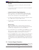
A. (BMC) VGA Enable
B. BMC IPMI Enable
A
B
(BMC) VGA Enable/Dis-
able Jumper Settings
(JPG1)
Both Jumpers Defi nition
Pins 1-2 Enabled
Pins 2-3 Disabled
(BMC) VGA Enable
JPG1 allows you to enable or disable the
onboard VGA connection supported by
the Winbond WPCM450-R Controller. The
default position is on pins 1 and 2 to en-
able VGA. See the table on the right for
jumper settings.
BMC IPMI Enable/Disable
Jumper Settings (JPB)
Both Jumpers Defi nition
Pins 1-2 Enabled
Pins 2-3 Disabled
BMC IPMI Enable (X7SB3-F only)
JPB allows you to enable or disable BMC
(Baseboard Management Control) Chip
and the onboard IPMI connections. This
jumper is to be used together with the IPMI
settings in the BIOS. If this jumper is set
to Enabled, please enable IPMI settings
in the BIOS as well and vice versa. The
default position is on pins 1 and 2 to En-
able BMC. See the table on the right for
jumper settings.