
User`s manual


2-16
X7SB3/X7SB3-F User's Manual
J27
J8
JLAN1
B1
COM2
JWOR
JAR
JPF
J3P
J45
J44
JPG1
JPL1
JPUSB1
JPS2
JPS1
JLED1
JWD
JPW1
JWOL
3-SGPIO2
Fan5
Fan1
Fan4
Fan2
JBT1
PW4
PCI1
SAS7
SAS0
SAS5
SAS6
SAS4
SAS3
SAS2
SAS1
SPKR1
J48
J47
JD1
LE2
LE4
LE5
LE1
COM1
JF1
JPW2
DIMM4
DIMM3
DIMM2
DIMM1
CPU
KB/MOUSE
VGA
LE3
USB2
USB6/7
USB4/5
JLAN2
Battery
LAN
CTRL1
PCI-E x8
LAN
CTRL2
Winbond
IPMI/VGA CTRL
Winbond
83627DHG
SI/O
JI2C2
JI2C1
Intel
ICH9
(South Bridge)
3-SGPIO1
LSI
1068E
SAS CTRL
USB3
Floppy
FP CTRL
Fan3
Intel
3210 MCH
(North Bridge)
JS1
JS2
I-SATA0
I-SATA1
PCI 33 MHz
BIOS
82574L
Intel
82574L
Intel
WPCM450-R
X7SB3
24-pin ATX PWR
8-pin PWR
I-Button
JPL2
JPB
JL1
LED1
DIMM1A
DIMM2A
DIMM1B
DIMM2B
USB0/1
IPMI LAN
(X7SB3-F)
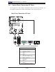
Required Connections
A. 24-pin ATX PWR
B. 8-pin Processor PWR
A
B
2-6 Connecting to the Headers and Connectors
Power Connectors
ATX Power Connector
A 24-pin main power supply connector
(JPW1) and an 8-pin CPU PWR connector
(JPW2) are located on the motherboard.
These power connectors meet the SSI
EPS 12V specifi cation. For the 8-pin PWR
(JPW2), please refer to the item listed
below. See the table on the right for pin
defi nitions.
Processor Power Connector
In addition to the Primary ATX power con-
nector (above), the 12V 8-pin CPU PWR
connector at JPW2 must also be connected
to your power supply. See the table on the
right for pin defi nitions.
Required Connection
12V 8-pin Power CPU
Connector
Pin Defi nitions
Pins Defi nition
1 through 4 Ground
5 through 8 +12V
ATX Power 24-pin Connector
Pin Defi nitions
Pin# Defi nition Pin # Defi nition
13 +3.3V 1 +3.3V
14 -12V 2 +3.3V
15 COM 3 COM
16 PS_ON 4 +5V
17 COM 5 COM
18 COM 6 +5V
19 COM 7 COM
20 Res (NC) 8 PWR_OK
21 +5V 9 5VSB
22 +5V 10 +12V
23 +5V 11 +12V
24 COM 12 +3.3V