
User`s manual

Chapter 2: Installation
2-19
LAN1
®
S
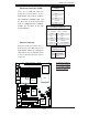
UPER X7DVA
SCSI Chan. A
IDE1
Fan4
SCSI Chan. B
PCI 33 MHz
JD1
GLAN
CTRLR
North Bridge
COM1
ATX PWR
8-Pin PWR
24-Pin
CPU2
South
Bridge
Fan1
SATA1
Slot1
Slot2
Slot3
PCI-Exp. x8
ZCR
JPL2
Slot5
DIMM 1A (Bank 1)
DIMM 1B (Bank 1)
DIMM 1C (Bank 1)
DIMM 2A (Bank 2)
DIMM 2B (Bank 2)
DIMM 2C (Bank 2)
JBT1
KB/
Mouse
USB 0/1
5000V
BIOS
LAN2
Fan6
JPWF
JAR
PWR I
2
C
VGA
PCI-X 100 MHz
(Green Slot)
JPG1
JWD
Printer
JPL1
JI
2
C1
JI
2
C2
JWOR
Floppy
JWOL
Fan2
CPU1
LE2
LE3
LE1
USB4/5
USB2/3
JPF
Buzzer
ESB2
VGA
CTRLR
SGPIO1
SGPIO2
JL1
VGA
Memory
S I/O
COM2
J2
J8B1
J7B3
J7B2
J7B1
J1
Battery
Slot6
SIM_LP
IPMI
PCI-Exp. x4
PCI-X 100 MHz
JPA1
SCSI
CTRLR
SATA0
SATA3
SATA2
SATA5
SATA4
JPA2
JPA3
JP1
JF1
FP CNTLR
Fan3
LE4
LE5
Fan5
D31
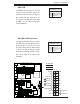
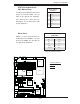
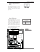
Power LED/Speaker
On the JD1 header, pins 1-3 are for
a power LED and pins 4-7 are for the
speaker. See the table on the right
for speaker pin defi nitions. Note: The
speaker connector pins are for use
with an external speaker. If you wish to
use the onboard speaker, you should
close pins 6-7 with a jumper.
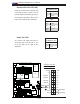
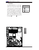
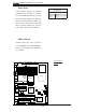
GLAN 1/2 (Giga-bit Ethernet
Ports)
Two G-bit Ethernet ports are desig-
nated JLAN1 and JLAN2 on the I/O
backplane. This port accepts RJ45
type cables.
Speaker Connector
Pin Defi nitions
Pin Setting Defi nition
Pins 6-7 Internal Speaker
Pins 4-7 External Speaker
A
B
A. GLAN1/2
B. PWR LED/Speaker
GLAN1
GLAN2