
Datasheet


Chapter 2: Installation
2-29
LAN1/2
®
JLAN1
S
UPER X7DA3
Fan1
8-pin PWR
FP Control
SPK
PW LED
JOH1
Fan3
IDE1
Floppy
Fan4
SATA3
SATA5
USB4/5
SMB
PCI-X 100 MHz ZCR (Gre
en Slot)
PCI-X 133 MHz
JWD
Battery
GLAN
CTLR
PCI-Exp x4
North Bridge
COM1
Fan6
Fan5
ATX PWR
4-Pin
PWR
J3P
Parrallel
Port
24-Pin
SAS
Controller
PXH
CPU1
CPU2
South
Bridge
Fan7
JAR
J17
PSF
JPW3
Fan2
Compact Flash
LE1
Fan8
JCF1
JWF1
SATA2
SATA4
SATA1
SATA0
JL1
Slot1
Slot2
Slot3
PCI-X 133 MHz
Slot4
JPL2
Slot5
PCI-33MHz
Slot6
PCI-Exp x16
SIM LP IPMI
Slot7
J7B1
J7B2
J7B3
J8B1
J8B2
J8B3
J9B1
J9B2
DIMM 1A (Bank 1)
DIMM 1B (Bank 1)
DIMM 2A (Bank 2)
DIMM 2B (Bank 2)
DIMM 3A (Bank 3)
DIMM 3B (Bank 3)
DIMM 4A (Bank 4)
DIMM 4B (Bank 4)
JBT1
JWOL
JWOR
COM2
KB/
Mouse
USB 0/
1/2/3
JPAC
JI
2
C2
JI
2
C3
JI
2
C4
Greencreek
BIOS
CPU
Fan 1
CD2 CD1
JPL1
JI
2
C1
CPU
Fan2
Line-In/
Line-
Out
Mic
SGPIO1
SGPIO2
JS10
SAS4-7
SAS0
-3
JPS1
ACT0-3
PRES0-3
PRES4-7
ACT4-7
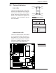
GLAN LEDs
There are two GLAN ports on the moth-
erboard. Each Gigabit Ethernet LAN port
has two LEDs. The green LED indicates
activity, while the Link LED may be green,
amber or off to indicate the speed of the
connection. See the tables at right for
more information.
2-8 Onboard Indicators
Activity
LED
GLAN Activity Indicator
Color Status Defi nition
Green Flashing Active
GLAN Link Indicator
LED Color Defi nition
Off No Connection or 10 Mbps
Green (On) 100 Mbps
Amber (On) 1 Gbps
A
B
A. GLAN Port1 LEDs
B. Standby PWR LED
Link
LED
Activity
LED
Link
LED
Onboard Power LED
There is an Onboard Power LED located
on the motherboard. When this LED is on,
the system is on. Be sure to turn off the
system and unplug the power cord before
removing or installing components. See
the layout below for the LED location.
Rear View (When viewing it
from the back of the system)