
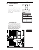
Datasheet


2-26
X7DA3 User's Manual
LAN1/2
®
JLAN1
S
UPER X7DA3
Fan1
8-pin PWR
FP Control
SPK
PW LED
JOH1
Fan3
IDE1
Floppy
Fan4
SATA3
SATA5
USB4/5
SMB
PCI-X 100 MHz ZCR (Gre
en Slot)
PCI-X 133 MHz
JWD
Battery
GLAN
CTLR
PCI-Exp x4
North Bridge
COM1
Fan6
Fan5
ATX PWR
4-Pin
PWR
J3P
Parrallel
Port
24-Pin
SAS
Controller
PXH
CPU1
CPU2
South
Bridge
Fan7
JAR
J17
PSF
JPW3
Fan2
Compact Flash
LE1
Fan8
JCF1
JWF1
SATA2
SATA4
SATA1
SATA0
JL1
Slot1
Slot2
Slot3
PCI-X 133 MHz
Slot4
JPL2
Slot5
PCI-33MHz
Slot6
PCI-Exp x16
SIM LP IPMI
Slot7
J7B1
J7B2
J7B3
J8B1
J8B2
J8B3
J9B1
J9B2
DIMM 1A (Bank 1)
DIMM 1B (Bank 1)
DIMM 2A (Bank 2)
DIMM 2B (Bank 2)
DIMM 3A (Bank 3)
DIMM 3B (Bank 3)
DIMM 4A (Bank 4)
DIMM 4B (Bank 4)
JBT1
JWOL
JWOR
COM2
KB/
Mouse
USB 0/
1/2/3
JPAC
JI
2
C2
JI
2
C3
JI
2
C4
Greencreek
BIOS
CPU
Fan 1
CD2 CD1
JPL1
JI
2
C1
CPU
Fan2
Line-In/
Line-
Out
Mic
SGPIO1
SGPIO2
JS10
SAS4-7
SAS0-3
JPS1
ACT0-3
PRES0-3
PRES4-7
ACT4-7
3rd PWR Supply PWR Fault
Detect (J3P)
The system can notify you in the event
of a power supply failure. This feature
available when three power supply units
are installed in the chassis with one act-
ing as a backup. If you only have one
or two power supply units installed, you
should disable this (the default setting)
with J3P to prevent false alarms.
3rd PWR Supply PWR Fault
Jumper Settings
Jumper Setting Defi nition
Closed Enabled
Open Disabled (*Default)
A
B
A. 3rd PWR Fail
B. Audio Enable
Audio Enable(JPAC)
Pin# Defi nition
1-2 Enabled (*default)
2-3 Disabled
Audio Enable/Disable
JPAC enables or disables Audio Controller
on the motherboard. See the table on the
right for jumper settings. The default set-
ting is enabled.