
Datasheet


2-16
X7DA3 User's Manual
LAN1/2
®
JLAN1
S
UPER X7DA3
Fan1
8-pin PWR
FP Control
SPK
PW LED
JOH1
Fan3
IDE1
Floppy
Fan4
SATA3
SATA5
USB4/5
SMB
PCI-X 100 MHz ZCR (Gre
en Slot)
PCI-X 133 MHz
JWD
Battery
GLAN
CTLR
PCI-Exp x4
North Bridge
COM1
Fan6
Fan5
ATX PWR
4-Pin
PWR
J3P
Parrallel
Port
24-Pin
SAS
Controller
PXH
CPU1
CPU2
South
Bridge
Fan7
JAR
J17
PSF
JPW3
Fan2
Compact Flash
LE1
Fan8
JCF1
JWF1
SATA2
SATA4
SATA1
SATA0
JL1
Slot1
Slot2
Slot3
PCI-X 133 MHz
Slot4
JPL2
Slot5
PCI-33MHz
Slot6
PCI-Exp x16
SIM LP IPMI
Slot7
J7B1
J7B2
J7B3
J8B1
J8B2
J8B3
J9B1
J9B2
DIMM 1A (Bank 1)
DIMM 1B (Bank 1)
DIMM 2A (Bank 2)
DIMM 2B (Bank 2)
DIMM 3A (Bank 3)
DIMM 3B (Bank 3)
DIMM 4A (Bank 4)
DIMM 4B (Bank 4)
JBT1
JWOL
JWOR
COM2
KB/
Mouse
USB 0/
1/2/3
JPAC
JI
2
C2
JI
2
C3
JI
2
C4
Greencreek
BIOS
CPU
Fan 1
CD2 CD1
JPL1
JI
2
C1
CPU
Fan2
Line-In/
Line-
Out
Mic
SGPIO1
SGPIO2
JS10
SAS4-7
SAS0
-3
JPS1
ACT0-3
PRES0-3
PRES4-7
ACT4-7
Fan Headers
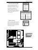
The X7DA3 has eight chassis/system
fan headers (Fan1 to Fan8), including
two CPU Fans (Fans 7/8). (*Note: all
these fans are 4-pin fans. However,
Pins 1-3 of the fan headers are back-
ward compatible with the traditional
3-pin fans). See the table on the right
for pin defi nitions. (*The onboard fan
speeds are controlled by Thermal
Management via BIOS Hardware
Monitor in the Advanced Setting
.
Note: The Manufacturer Default is set
to Disabled to allow the fans to run at
the full speed at all time. When using
Thermal Management setting, please
use all 3-pin fans or all 4-pin fans on
the motherboard.)
Fan Header
Pin Defi nitions (Fan1-8)
Pin# Defi nition
1 Ground
2 +12V
3 Tachometer
4 PWR Modulation
B
C
G
F
E
A
A. Fan 1
B. Fan 2
C. Fan 3
D. Fan 4
E. Fan 5
F. Fan 6
G. Fan 7 (CPU Fan 1)
H. Fan 8 (CPU Fan 2)
H