
User`s manual
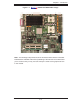
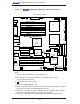

Table of Contents
v
Reset Button .................................................................................... 2-12
Power Button ..................................................................................... 2-12
2-5 Connectors/IO Ports/Headers ......................................................................... 2-13
ATX Power Connector .......................................................................... 2-13
Processor Power Connector ................................................................. 2-13
Chassis Intrusion .................................................................................... 2-14
Universal Serial Bus (USB0/1) ................................................................ 2-14
Serial Ports ............................................................................................. 2-15
Extra Universal Serial Bus Headers ....................................................... 2-15
Fan Headers .......................................................................................... 2-16
ATX PS/2 Keyboard and Mouse Ports ..................................................... 2-16
Power LED/Speaker Header (JD1) ........................................................ 2-17
GLAN (Ethernet Port) ............................................................................... 2-17
Wake-On-Ring .......................................................................................... 2-18
Wake-On-LAN .......................................................................................... 2-18
SMB .......................................................................................................... 2-19
SMB Power .............................................................................................. 2-19
Power Fault .............................................................................................. 2-20
Alarm Reset .............................................................................................. 2-20
Overheat LED ........................................................................................... 2-21
3rd Power Supply Power Fault Detect ..................................................... 2-21
2-6 Jumper Settings ............................................................................................ 2-22
Explanation of Jumpers .......................................................................... 2-22
GLAN Enable/Disable ............................................................................ 2-22
CMOS Clear ........................................................................................... 2-23
Watch Dog ................................................................................................ 2-23
SCSI Enable/Disable ............................................................................... 2-24
SCSI Channel A/B Termination ................................................................ 2-24
VGA Enable .............................................................................................. 2-25
2-7 Onboard Indicators ....................................................................................... 2-26
GLAN LEDs .............................................................................................. 2-26
SCSI Channel Activity LED Indicators ..................................................... 2-26
2-8 Parallel Port, Floppy/Hard Disk Drive and SCSI Connections ..................... 2-27
Parallel Port Connector ........................................................................... 2-27
Floppy Connector .................................................................................... 2-28
IPMI 2.0 Socket ....................................................................................... 2-28
IDE Connectors ....................................................................................... 2-29
SCSI Connectors ..................................................................................... 2-30