
User`s manual

Chapter 2: Installation
2-23
GLAN1
®
JLAN1
S
UPER X6DH8-G2+
GLAN2
DIMM 2B (Bank 2)
DIMM 2A (Bank 2)
DIMM 3B (Bank 3)
DIMM 3A (Bank 3)
DIMM 4B (Bank 4)
DIMM 4A (Bank 4)
DIMM 1A (Bank 1)
DIMM 1B (Bank 1)
Fan1
8-pin
PWR
PWR
SMBus
FP Control
SPK
PW LED
JP15
Fan2
JOH1
Fan8
Fan3
JL1
IPMI
IDE1
Floppy
COM2
BIOS
JWD
JPA1
SCSI CH A
Ultra 320
SCSI CH B
Fan4
JPA2
7902
CTRL
SATA0
SATA1
USB2/3
SMBUS
Speake
r
PCI-X #1 100 MHz ZCR
PCI-X #2 100 MHz
PCI-X
#3 133 MHz
WOR
Battery
JPL1
GLAN
CTLR
RAGE-
X
USB4
82546
GLAN
Enable
X4 PCI-Epx #4
X8 PCI-Epx #5
X8 PCI-Epx #6
Super
I/O
North
Bridge
JPG1
VGA
COM1
USB0/1
KB/
Mouse
Fan6
Fan5
ATX PWR
4-Pin
PWR
JPF
Parrallel
Port
24-Pin
Fan7
JP14
SCSI
JPA3
CPU 1
CPU 2
JBT1
ICH5R
SI/O
PXH
WOL
Ultra 320
IDE2
JP12
JP13
JLAN1
JLAN2
SEPC
South
Bridge
E7520
J27
DA1
DA2
LE1
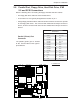
Watch Dog
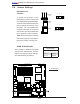
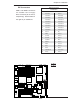
JWD controls Watch Dog, a system
monitor that takes action when a soft-
ware application hangs. Close pins
1-2 to reset the system if a program
freezes. Close pins 2-3 to generate a
non-maskable interrupt for the program
that hangs. (This requires software
implementation). Watch Dog must also
be enabled in the BIOS.
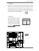
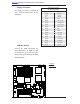
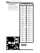
CMOS Clear
JBT1 is used to clear CMOS. Instead of pins, this "jumper" consists of contact
pads to prevent the accidental clearing of CMOS. To clear CMOS, use a metal
object such as a small screwdriver to touch both pads at the same time to short
the connection. Always remove the AC power cord from the system before clear-
ing CMOS. Note: For an ATX power supply, you must completely shut down the
system, remove the AC power cord and then short JBT1 to clear CMOS. Do not
use the PW_ON connector to clear CMOS.
Watch Dog
Jumper Settings (JWD)
Jumper Setting Defi nition
Pins 1-2 Reset
Pins 2-3 NMI
Open Disabled
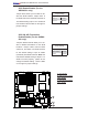
B
A
A. CMOS Clear
B. Watch Dog