
User`s manual


2-20
X6DH8-G2+/X6DHE-G2+ User's Manual
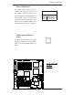
Power Fault
Connect a cable from your power sup-
ply to the Power Fault header (JP12)
to provide warning of power supply
failure. This warning signal is passed
through the PWR_LED pin to indicate
an occurrence of power failure on the
chassis. You need to use this header
(JP12) with the Alarm Reset header
(JP14) together for it to work prop-
erly. See the table on the right for pin
defi nitions.
Note: This feature is only available when using
Supermicro's triple redundant power supplies.
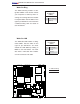
Alarm Reset (JP14)
The system will notify you in the
event of a power supply failure. Use
this feature to clear alarm when
Supermicro's redundant power supply
units are installed in the chassis. If
you only have a single power supply
installed, you should leave the pins
open (the default setting) to prevent
false alarms. See the table on the right
for jumper settings.
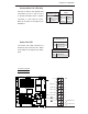
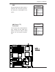
PWR Fault
Pin Defi nitions
Pin# Defi nition
1 Pin 1 Fail Signal
2 Pin 2 Fail Signal
3 Pin 3 Fail Signal
4 Alarm Reset
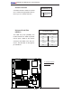
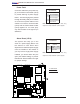
Alarm Reset
Pin Defi nitions
Jumper
Position Defi nition
Open Normal (De-
fault)
Short Clear Alarm
Note: This feature is only available when using
Supermicro's triple redundant power supplies.
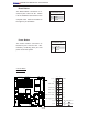
B
A
A. PWR Fault
B. Alarm Reset
GLAN1
®
JLAN1
S
UPER X6DH8-G2+
GLAN2
DIMM 2B (Bank 2)
DIMM 2A (Bank 2)
DIMM 3B (Bank 3)
DIMM 3A (Bank 3)
DIMM 4B (Bank 4)
DIMM 4A (Bank 4)
DIMM 1A (Bank 1)
DIMM 1B (Bank 1)
Fan1
8-pin
PWR
PWR
SMBus
FP Control
SPK
PW LED
JP15
Fan2
JOH1
Fan8
Fan3
JL1
IPMI
IDE1
Floppy
COM2
BIOS
JWD
JPA1
SCSI CH A
Ultra 320
SCSI CH B
Fan4
JPA2
7902
CTRL
SATA0
SATA1
USB2/3
SMBUS
Speake
r
PCI-X #1 100 MHz ZCR
PCI-X #2 100 MHz
PCI-X
#3 133 MHz
WOR
Battery
JPL1
GLAN
CTLR
RAGE-
X
USB4
82546
GLAN
Enable
X4 PCI-Epx #4
X8 PCI-Epx #5
X8 PCI-Epx #6
Super
I/O
North
Bridge
JPG1
VGA
COM1
USB0/1
KB/
Mouse
Fan6
Fan5
ATX PWR
4-Pin
PWR
JPF
Parrallel
Port
24-Pin
Fan7
JP14
SCSI
JPA3
CPU 1
CPU 2
JBT1
ICH5R
SI/O
PXH
WOL
Ultra 320
IDE2
JP12
JP13
JLAN1
JLAN2
SEPC
South
Bridge
E7520
J27
DA1
DA2
LE1