
User`s manual


Chapter 2: Installation
2-11
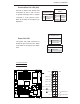
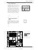
Overheat/Fan Fail LED (OH)
Connect an LED to the OH/Fan Fail
connection on pins 7 and 8 of JF1
to provide warnings when a system
overheat or a fan failure occurs.
Refer to the table on the right for pin
defi nitions.
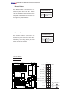
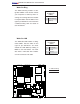
Power Fail LED
The Power Fail LED connection is
located on pins 5 and 6 of JF1. Refer
to the table on the right for pin defi ni-
tions.
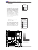
A. OH/Fan Fail LED
B. PWR Supply Fail
OH/Fan Fail LED
Pin Defi nitions (JF1)
Pin# Defi nition
7 Vcc
8 HD Active
OH/Fan Fail Indicator
Status
State Defi nition
Off Normal
On Overheat
Flashing Fan Fail
PWR Fail LED
Pin Defi nitions (JF1)
Pin# Defi nition
5 PWR Fail LED-
6 PWR Fail LED+
PWR Fail Indicator Status
State Defi nition
Red PWR Failure
Power Butto
n
OH/Fan Fail LED
1
NIC1 LED
2
HDD LED
Pwr
Vcc
Vcc
Vcc
Ground
1920
X
Ground
NMI
X
NIC2 LED
Vcc
PWR LED
Vcc
Ground
Reset Butto
n
Vcc
Power Supply Fail
B
A
GLAN1
®
JLAN1
S
UPER X6DH8-G2+
GLAN2
DIMM 2B (Bank 2)
DIMM 2A (Bank 2)
DIMM 3B (Bank 3)
DIMM 3A (Bank 3)
DIMM 4B (Bank 4)
DIMM 4A (Bank 4)
DIMM 1A (Bank 1)
DIMM 1B (Bank 1)
Fan1
8-pin
PWR
PWR
SMBus
FP Control
SPK
PW LED
JP15
Fan2
JOH1
Fa
n8
Fan3
JL1
IPMI
IDE1
Floppy
COM2
BIOS
JWD
JPA1
SCSI CH A
Ultra 320
SCSI CH B
Fan4
JPA2
7902
CTRL
SATA
0
SATA1
USB2/3
SMBUS
Speake
r
PCI-X #1 100 MHz ZCR
PCI-X
#2 100 MHz
PCI-X #3 133 MHz
WOR
Battery
JPL1
GLAN
CTLR
RAGE-
X
USB4
82546
GLAN
Enable
X4 PCI-Epx #4
X8 PC
I-Epx #5
X8 PCI-Epx #6
Super
I/O
North
Bridge
JPG1
VGA
COM1
USB0/1
KB/
Mouse
Fan6
Fan5
ATX PWR
4-Pin
PWR
JPF
Parrallel
Port
24-Pin
Fan7
JP14
SCSI
JPA3
CPU 1
CPU 2
JBT1
ICH5R
SI/O
PXH
WOL
Ultra
320
IDE2
JP12
JP13
JLAN1
JLAN2
SEPC
South
Bridge
E7520
J27
DA1
DA2
LE1