
User`s manual

1-4
X6DH8-G2+/X6DHE-G2+ User's Manual
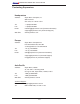
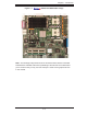
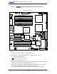
Figure 1-2. X6DH8-G2+/X6DHE-G2+ Motherboard Layout
(not drawn to scale)
Notes:
1. Jumpers not indicated are for test purposes only.
2. See Chapter 2 for detailed information on jumpers, I/O ports and
JF1 front panel connections.
3. " " indicates the location of Pin 1.
4. SCSI is for the X6DH8-G2+ only
5. SEPC: Supermicro Enhanced Power Connector, specially designed to support
Supermicro 2U Riser Card (CSE-RR2UE-AX) only.
6. When the LE1 LED is on, the 5V Standby PWR is on. Maker sure to unplug
the power cord before installing or removing components.
7. Be sure to install the Zero Channel RAID card (ZCR) in the Green Slot.
GLAN1
®
JLAN1
S
UPER X6DH8-G2+
GLAN2
DIMM
2B
(Bank 2)
DIMM 2A (Bank 2)
DIMM 3B (Bank 3)
DIMM 3A (Bank 3)
DIMM
4B (Bank 4)
DIMM 4A (Bank 4)
DIMM 1A (Bank 1)
DIMM 1B (Bank 1)
Fan1
8-pin
PWR
PWR
SMBus
JF1
FP Control
JD1
SPK
PW LED
JP15
Fan2
JOH1
OH
Fa
n8
Fan3
CH Intru
JL1
WD Ena.
IPMI
IDE1
Floppy
COM2
J20
BIOS
JWD
JPA1
SCSI CH A
Ultra 320
SCSI CH B
Fan4
JPA2
7902
CTRL
SATA0
SATA1
USB2/3
SMBUS
Speaker
PCI-X #1 100 MHz ZCR
PCI-X #2 100 MHz
PCI-X #3 133 MHz
WOR
Battery
JPL1
GLAN
CTLR
RAGE-
X
USB4
82546
GLAN
Enable
X4 PCI-Epx #4
X8 PC
I-Epx #5
X8 PCI-Epx #6
J12
J13
J14
J15
J16
J17
Super
I/O
North
Bridge
JPG1
VGA
COM1
USB0/1
KB/
Mouse
Fan6
Fan5
ATX PWR
4-Pin
PWR
JPF
Parrallel
Port
J11
J32
24-Pin
Force PWR ON
VGA
Enable
Fan7
J24
J1D1
J1B4
JP14
J3
J4
JP8
J7
SCSI
JPA3
JD2
J22
CPU 1
CPU 2
Alrm
Reset
JWOR
SCSI
Enable
SCSI CHA Term.
Clr
CMOS
JBT1
ICH5R
SI/O
PXH
J9
J5
J6
J23
WOL
JWOL
JS1
JS2
Ultra 320
JA2
JA1
IDE2
JP12
PW
Fault
JP13
3rd PS
Alarm
SCSI CHB Term.
J8
JLAN1
JLAN2
SEPC
J33
South
Bridge
E7520
J27
DA1
DA2
LE1