
User Manual


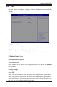


Table Of Contents
- Preface
- Chapter 1 Introduction
- Chapter 2 Installation
- 2-1 Standardized Warning Statements
- 2-2 Static-Sensitive Devices
- 2-3 Motherboard Installation
- 2-4 Memory Support
- 2-5 Connectors/IO Ports
- 2-6 Connecting Cables
- ATX PWR, DC PWR and HDD PWR Connectors (JPW1, PJ1, J6)
- Fan Headers (FAN1 ~ FAN4) (FAN4 is available on PCB 2.00 only)
- Chassis Intrusion
- System Management Bus Header
- DOM PWR Connector
- TPM Header/Port 80 Header
- Overheat LED Header
- Speaker
- Standby Power
- I-SGPIO1/I-SGPIO2
- NVMe I2C Header
- Power SMBus (I2C) Connector (available on PCB 2.00 only)
- System Management Bus Header
- GPIO Header
- ATX PWR, DC PWR and HDD PWR Connectors (JPW1, PJ1, J6)
- 2-7 Jumper Settings
- 2-8 Onboard Indicators
- 2-9 SATA Connections
- Chapter 3 Troubleshooting
- Chapter 4 BIOS
- Appendix A BIOS Error Beep Codes
- Appendix B Software Installation Instructions
- Appendix C UEFI BIOS Recovery Instructions
- Appendix D Dual Boot Block

Chapter 4: AMI BIOS
4-31
Station MAC Address
This item displays the Station MAC address for this computer. Mac addresses are
6 two-digit hexadecimal numbers.
Gateway IP Address
This item displays the Gateway IP address for this computer. This should be in
decimal and in dotted quad form (i.e., 172.31.0.1).
IPMI Function Support
Use this feature to enable or disable IPMI support within the BIOS. The options
are Enabled and Disabled. When Disabled, the motherboard powers on quickly
by removing BIOS control for extended IPMI features. The Disable option is for
applications that require faster power on time wthout using Supermicro Update
Manager (SUM) or extended IPMI features. The BMC network conguration in the
BIOS setup is also invalid when IPMI Function Support is disabled. General BMC
function and motherboard health monitor such as temperature and fan control are
still active even when this option is disabled.