
User Manual


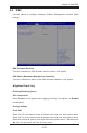


Table Of Contents
- Preface
- Chapter 1 Introduction
- Chapter 2 Installation
- 2-1 Standardized Warning Statements
- 2-2 Static-Sensitive Devices
- 2-3 Motherboard Installation
- 2-4 Memory Support
- 2-5 Connectors/IO Ports
- 2-6 Connecting Cables
- ATX PWR, DC PWR and HDD PWR Connectors (JPW1, PJ1, J6)
- Fan Headers (FAN1 ~ FAN4) (FAN4 is available on PCB 2.00 only)
- Chassis Intrusion
- System Management Bus Header
- DOM PWR Connector
- TPM Header/Port 80 Header
- Overheat LED Header
- Speaker
- Standby Power
- I-SGPIO1/I-SGPIO2
- NVMe I2C Header
- Power SMBus (I2C) Connector (available on PCB 2.00 only)
- System Management Bus Header
- GPIO Header
- ATX PWR, DC PWR and HDD PWR Connectors (JPW1, PJ1, J6)
- 2-7 Jumper Settings
- 2-8 Onboard Indicators
- 2-9 SATA Connections
- Chapter 3 Troubleshooting
- Chapter 4 BIOS
- Appendix A BIOS Error Beep Codes
- Appendix B Software Installation Instructions
- Appendix C UEFI BIOS Recovery Instructions
- Appendix D Dual Boot Block

4-26
X10SDV Mini-ITX Series Motherboard User’s Manual
TPM State
Select Enabled to use TPM (Trusted Platform Module) settings for system data
security. The options are Disabled and Enabled.
Note: The system will reboot for the change on TPM State to take effect.
Pending Operation
Use this item to schedule a TPM-related operation to be performed by a security
device for TPM support. The options are None, Enable Take Ownership, Disable
Take Ownership, and TPM Clear.
Note: The computer will reboot to carry out a pending TPM operation and
change TPM state for a TPM device.
Current Status Information
This feature indicates the status of the following TPM items:
TPM Enabled Status
TPM Active Status
TPM Owner Status
Intel TXT (LT-SX) Conguration
TXT Support
Intel TXT (Trusted Execution Technology) helps protect against software-based
attacks to ensure the security, condentiality, and integrity of all data stored in the
system. The options are Enabled and Disabled.