
User Manual


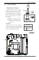


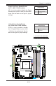


Table Of Contents
- Preface
- Chapter 1 Introduction
- Chapter 2 Installation
- 2-1 Standardized Warning Statements
- 2-2 Static-Sensitive Devices
- 2-3 Motherboard Installation
- 2-4 Memory Support
- 2-5 Connectors/IO Ports
- 2-6 Connecting Cables
- ATX PWR, DC PWR and HDD PWR Connectors (JPW1, PJ1, J6)
- Fan Headers (FAN1 ~ FAN4) (FAN4 is available on PCB 2.00 only)
- Chassis Intrusion
- System Management Bus Header
- DOM PWR Connector
- TPM Header/Port 80 Header
- Overheat LED Header
- Speaker
- Standby Power
- I-SGPIO1/I-SGPIO2
- NVMe I2C Header
- Power SMBus (I2C) Connector (available on PCB 2.00 only)
- System Management Bus Header
- GPIO Header
- ATX PWR, DC PWR and HDD PWR Connectors (JPW1, PJ1, J6)
- 2-7 Jumper Settings
- 2-8 Onboard Indicators
- 2-9 SATA Connections
- Chapter 3 Troubleshooting
- Chapter 4 BIOS
- Appendix A BIOS Error Beep Codes
- Appendix B Software Installation Instructions
- Appendix C UEFI BIOS Recovery Instructions
- Appendix D Dual Boot Block

2-28
X10SDV Mini-ITX Series Motherboard User’s Manual
JF1
JPI2C1
COM1
I-SATA0
JGPIO1
JSMB1
JPTG1
JBR1
JI2C1
JI2C2
JPG1
JPL1
JPME1
JPME2
JPUSB1
JWD1
DESIGNED IN USA
SRW2
SRW1
JUIDB1
J21
I-SGPIO2
I-SGPIO1
JL1
JOH1
JD1
PJ1
JSTBY1
JPW1
LED8
C
LED7
A
C
LED3
A
C
LEDM1
A
C
BT1
FAN4
FAN3
FAN2
FAN1
VGA
JTPM1
JSD1
I-SATA1
I-SATA4
I-SATA2
I-SATA3
I-SATA5
DIMMB2
DIMMA2
DIMMB1
DIMMA1
JIPMB1
JNVI2C1
X10SDV-F
REV: 2.00
LAN3/4
LAN1/2
PCI-E 3.0 X16
PWR
ON
RST
NIC2
OH
FF
X
NIC1
PWR
LED
HDD
LED
JF1:
USB 2/3
USB 0/1(3.0)
USB 4/5
SLOT7
JBT1
IPMI_LAN
J6
Intel
D-1500
BMC
AST2400
i350
A. Clear CMOS
B. JI
2
C1
C. JI
2
C2
PCI Slot SMB Enable
Jumper Settings
Pin# Denition
1-2 Enabled
2-3 Disabled (Default)
PCI-E Slot SMB Enable (I
2
C1/I
2
C2)
Use jumpers I
2
C1/I
2
C2 to enable PCI
SMB (System Management Bus) support
to improve system management for the
onboard PCI-E slot. See the table on the
right for jumper settings.
C
A
B
CMOS Clear
JBT1 is used to clear CMOS. Instead of pins, this "jumper" consists of contact pads
to prevent accidental clearing of CMOS. To clear CMOS, use a metal object such
as a small screwdriver to touch both pads at the same time to short the connec-
tion. Always remove the AC power cord from the system before clearing CMOS.
Note 1: For an ATX power supply, you must completely shut down the
system, remove the AC power cord, and then short JBT1 to clear CMOS.
Note 2: Be sure to remove the onboard CMOS Battery before you short
JBT1 to clear CMOS.
Note 3: Clearing CMOS will also clear all passwords.