
User Manual
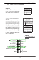
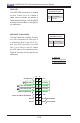


Table Of Contents
- Preface
- Chapter 1 Introduction
- Chapter 2 Installation
- 2-1 Standardized Warning Statements
- 2-2 Static-Sensitive Devices
- 2-3 Motherboard Installation
- 2-4 Memory Support
- 2-5 Connectors/IO Ports
- 2-6 Connecting Cables
- ATX PWR, DC PWR and HDD PWR Connectors (JPW1, PJ1, J6)
- Fan Headers (FAN1 ~ FAN4) (FAN4 is available on PCB 2.00 only)
- Chassis Intrusion
- System Management Bus Header
- DOM PWR Connector
- TPM Header/Port 80 Header
- Overheat LED Header
- Speaker
- Standby Power
- I-SGPIO1/I-SGPIO2
- NVMe I2C Header
- Power SMBus (I2C) Connector (available on PCB 2.00 only)
- System Management Bus Header
- GPIO Header
- ATX PWR, DC PWR and HDD PWR Connectors (JPW1, PJ1, J6)
- 2-7 Jumper Settings
- 2-8 Onboard Indicators
- 2-9 SATA Connections
- Chapter 3 Troubleshooting
- Chapter 4 BIOS
- Appendix A BIOS Error Beep Codes
- Appendix B Software Installation Instructions
- Appendix C UEFI BIOS Recovery Instructions
- Appendix D Dual Boot Block

Chapter 2: Installation
2-19
JF1
JPI2C1
COM1
I-SATA0
JGPIO1
JSMB1
JPTG1
JBR1
JI2C1
JI2C2
JPG1
JPL1
JPME1
JPME2
JPUSB1
JWD1
DESIGNED IN USA
SRW2
SRW1
JUIDB1
J21
I-SGPIO2
I-SGPIO1
JL1
JOH1
JD1
PJ1
JSTBY1
JPW1
LED8
C
LED7
A
C
LED3
A
C
LEDM1
A
C
BT1
FAN4
FAN3
FAN2
FAN1
VGA
JTPM1
JSD1
I-SATA1
I-SATA4
I-SATA2
I-SATA3
I-SATA5
DIMMB2
DIMMA2
DIMMB1
DIMMA1
JIPMB1
JNVI2C1
X10SDV-F
REV: 2.00
LAN3/4
LAN1/2
PCI-E 3.0 X16
PWR
ON
RST
NIC2
OH
FF
X
NIC1
PWR
LED
HDD
LED
JF1:
USB 2/3
USB 0/1(3.0)
USB 4/5
SLOT7
JBT1
IPMI_LAN
J6
Intel
D-1500
BMC
AST2400
i350
2-6 Connecting Cables
This section provides brief descriptions and pin-out denitions for onboard headers
and connectors. Be sure to use the correct cable for each header or connector.
A. 24-Pin ATX Power
B. 12V DC Power
C. 4-Pin HDD Power
ATX Power 24-pin Connector
Pin Denitions (JPW1)
Pin# Denition Pin # Denition
13 +3.3V 1 +3.3V
14 NC 2 +3.3V
15 COM 3 COM
16 PS_ON 4 +5V
17 COM 5 COM
18 COM 6 +5V
19 COM 7 COM
20 NC 8 PWR_OK
21 +5V 9 5VSB
22 +5V 10 +12V
23 +5V 11 +12V
24 COM 12 +3.3V
A
ATX PWR, DC PWR and HDD PWR
Connectors (JPW1, PJ1, J6)
The 24-pin ATX power connector at
JPW1 is used to provide power to the
motherboard. PJ1 is the 12V DC power
connector that provides alternative power
for special enclosure when the 24-pin
ATX power is not in use. The 4-pin HDD
power connector J6 provides power to
onboard HDD devices.
C
1
4
2
3
1
4
12V DC Power
Pin Denitions (PJ1)
Pin# Denition
1-2 GND
3-4 12V
4-Pin HDD Power
Pin Denitions (J6)
Pin# Denition
1 12V
2-3 GND
4 5V
B