
User Manual
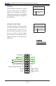


Table Of Contents
- Preface
- Chapter 1 Introduction
- Chapter 2 Installation
- 2-1 Standardized Warning Statements
- 2-2 Static-Sensitive Devices
- 2-3 Motherboard Installation
- 2-4 Memory Support
- 2-5 Connectors/IO Ports
- 2-6 Connecting Cables
- ATX PWR, DC PWR and HDD PWR Connectors (JPW1, PJ1, J6)
- Fan Headers (FAN1 ~ FAN4) (FAN4 is available on PCB 2.00 only)
- Chassis Intrusion
- System Management Bus Header
- DOM PWR Connector
- TPM Header/Port 80 Header
- Overheat LED Header
- Speaker
- Standby Power
- I-SGPIO1/I-SGPIO2
- NVMe I2C Header
- Power SMBus (I2C) Connector (available on PCB 2.00 only)
- System Management Bus Header
- GPIO Header
- ATX PWR, DC PWR and HDD PWR Connectors (JPW1, PJ1, J6)
- 2-7 Jumper Settings
- 2-8 Onboard Indicators
- 2-9 SATA Connections
- Chapter 3 Troubleshooting
- Chapter 4 BIOS
- Appendix A BIOS Error Beep Codes
- Appendix B Software Installation Instructions
- Appendix C UEFI BIOS Recovery Instructions
- Appendix D Dual Boot Block

2-18
X10SDV Mini-ITX Series Motherboard User’s Manual
Power Button
OH/Fan Fail/PWR Fail
1
NIC1 Activity LED
Reset Button
2
HDD LED
FP PWR LED
Reset
PWR
3.3 V
3.3V Stby
Ground
Ground
1516
(Power Fail LED on PCB 2.00) X
NIC2 Activity LED
3.3V Stby
3.3V Stby
UID LED
3.3V
Power Fail LED
(Available on PCB 2.00 only)
The Power Fail LED connection is lo-
cated on pins 5 and 6 of JF1. Refer to
the table on the right for pin denitions
Power Fail LED
Pin Denitions (JF1)
Pin# Denition
5 3.3V
6 PWR Supply Fail
(Floating on PCB 1.0x)
A. Power Supply Fail
(PCB 2.00 only)
A