
User Manual
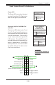
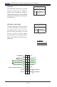


Table Of Contents
- Preface
- Chapter 1 Introduction
- Chapter 2 Installation
- 2-1 Standardized Warning Statements
- 2-2 Static-Sensitive Devices
- 2-3 Motherboard Installation
- 2-4 Memory Support
- 2-5 Connectors/IO Ports
- 2-6 Connecting Cables
- ATX PWR, DC PWR and HDD PWR Connectors (JPW1, PJ1, J6)
- Fan Headers (FAN1 ~ FAN4) (FAN4 is available on PCB 2.00 only)
- Chassis Intrusion
- System Management Bus Header
- DOM PWR Connector
- TPM Header/Port 80 Header
- Overheat LED Header
- Speaker
- Standby Power
- I-SGPIO1/I-SGPIO2
- NVMe I2C Header
- Power SMBus (I2C) Connector (available on PCB 2.00 only)
- System Management Bus Header
- GPIO Header
- ATX PWR, DC PWR and HDD PWR Connectors (JPW1, PJ1, J6)
- 2-7 Jumper Settings
- 2-8 Onboard Indicators
- 2-9 SATA Connections
- Chapter 3 Troubleshooting
- Chapter 4 BIOS
- Appendix A BIOS Error Beep Codes
- Appendix B Software Installation Instructions
- Appendix C UEFI BIOS Recovery Instructions
- Appendix D Dual Boot Block

Chapter 2: Installation
2-15
Power Butt
on
OH/Fan Fail/PWR Fail
1
NIC1 Activity LED
Reset Button
2
HDD LED
FP PWR LED
Reset
PWR
3.3 V
3.3V Stby
Ground
Ground
1516
(Power Fail LED on PCB 2.00)
X
NIC2 Activity LED
3.3V Stby
3.3V Stby
UID LED
3.3V
Power LED
The Power LED connection is located
on pins 15 and 16 of JF1. Refer to the
table on the right for pin denitions.
Power LED
Pin Denitions (JF1)
Pin# Denition
15 3.3V
16 PWR LED
Front Control Panel Pin Denitions
A. PWR LED
B. Overheat/Fan Fail/PWR Fail
C. UID LED
Overheat (OH)/Fan Fail/PWR Fail/
UID LED
Connect an LED cable to pins 7 and
8 of JF1 (Front Control Panel) to use
the Overheat/Fan Fail/Power Fail and
UID LED connections. The blue LED
on pin 7 works as the front panel UID
LED indicator. The red LED on pin 8
provides warnings of overheating, fan
failure or power failure. The red LED
takes precedence over the blue LED
by default. Refer to the table on the
right for pin denitions.
OH/Fan Fail/PWR Fail/
Blue_UID LED
Pin Denitions (JF1)
Pin# Denition
7 Blue_UID_LED
8 OH/Fan Fail/PWR Fail
A
C
B
Power LED
Pin Denitions (JF1)
State Denition
Off Normal
On Overheat
Blinking Fan/PWR Fail