
User Manual
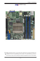
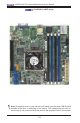


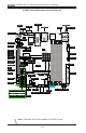


Table Of Contents
- Preface
- Chapter 1 Introduction
- Chapter 2 Installation
- 2-1 Standardized Warning Statements
- 2-2 Static-Sensitive Devices
- 2-3 Motherboard Installation
- 2-4 Memory Support
- 2-5 Connectors/IO Ports
- 2-6 Connecting Cables
- ATX PWR, DC PWR and HDD PWR Connectors (JPW1, PJ1, J6)
- Fan Headers (FAN1 ~ FAN4) (FAN4 is available on PCB 2.00 only)
- Chassis Intrusion
- System Management Bus Header
- DOM PWR Connector
- TPM Header/Port 80 Header
- Overheat LED Header
- Speaker
- Standby Power
- I-SGPIO1/I-SGPIO2
- NVMe I2C Header
- Power SMBus (I2C) Connector (available on PCB 2.00 only)
- System Management Bus Header
- GPIO Header
- ATX PWR, DC PWR and HDD PWR Connectors (JPW1, PJ1, J6)
- 2-7 Jumper Settings
- 2-8 Onboard Indicators
- 2-9 SATA Connections
- Chapter 3 Troubleshooting
- Chapter 4 BIOS
- Appendix A BIOS Error Beep Codes
- Appendix B Software Installation Instructions
- Appendix C UEFI BIOS Recovery Instructions
- Appendix D Dual Boot Block

1-10
X10SDV Mini-ITX Series Motherboard User’s Manual
Headers/Connectors
Connector Description
BT1 Onboard Battery
COM1 COM1 Header
FAN1 ~ FAN4 CPU/System Cooling Fans (FAN4 is on PCB 2.00 only)
IPMI LAN Dedicated IPMI LAN Port
I-SATA0 ~ I-SATA5 Intel® Serial ATA Ports (I-SATA0 supports SuperDOM)
I-SGPIO1, I-SGPIO2 Serial Link General Purpose I/O Headers
JGPIO1 General Purpose I/O Expander Header
J6 4-pin Power Connector for HDD use (To provide power
from the motherboard to onboard HDD devices)
J21 M.2 Socket (Shared with I-SATA0 when a SATA device is
installed in M.2)
JD1 Speaker (Pins 1-3: Power LED, Pins 4-7: Speaker)
JF1 Front Panel Control Header
JIPMB1 4-pin External SMbus I
2
C Header (for an IPMI Card)
JL1 Chassis Intrusion Header
JNVI
2
C1 NVMe I
2
C Header
JOH1 Overheat LED Header
JPI
2
C1 Power Supply SMBus I
2
C Header (On PCB 2.00 only)
JPW1 24-pin ATX Main Power Connector
JSD1 SATA DOM (Device On Module) Power Connector
Jumpers
Jumper Description Default
JBR1 BIOS Recovery Pins 1-2 (Normal)
JBT1 CMOS Clear Open: Normal, Short: Clear CMOS
JI
2
C1/JI
2
C2 SMB to PCI-Exp. Slots Pins 2-3 (Disabled)
JPG1 VGA Enable Pins 1-2 (Enabled)
JPL1 LAN1/LAN2 Enable Pins 1-2 (Enabled) (Not available on TLN2F)
JPME1 ME Recovery Pins 1-2 (Normal)
JPME2 Manufacturing Mode Pins 1-2 (Normal)
JPTG1 10Gb Ethernet Enable Pins 1-2 (Enabled)
JPUSB1 USB Wakeup Pins 1-2 (Enabled) (For USB0/1 Only)
JWD1 Watch Dog Enable Pins 1-2 (Reset)