
User Manual


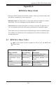


Table Of Contents
- Preface
- Chapter 1 Introduction
- Chapter 2 Installation
- 2-1 Standardized Warning Statements
- 2-2 Static-Sensitive Devices
- 2-3 Motherboard Installation
- 2-4 Memory Support
- 2-5 Connectors/IO Ports
- 2-6 Connecting Cables
- ATX PWR, DC PWR and HDD PWR Connectors (JPW1, PJ1, J6)
- Fan Headers (FAN1 ~ FAN4) (FAN4 is available on PCB 2.00 only)
- Chassis Intrusion
- System Management Bus Header
- DOM PWR Connector
- TPM Header/Port 80 Header
- Overheat LED Header
- Speaker
- Standby Power
- I-SGPIO1/I-SGPIO2
- NVMe I2C Header
- Power SMBus (I2C) Connector (available on PCB 2.00 only)
- System Management Bus Header
- GPIO Header
- ATX PWR, DC PWR and HDD PWR Connectors (JPW1, PJ1, J6)
- 2-7 Jumper Settings
- 2-8 Onboard Indicators
- 2-9 SATA Connections
- Chapter 3 Troubleshooting
- Chapter 4 BIOS
- Appendix A BIOS Error Beep Codes
- Appendix B Software Installation Instructions
- Appendix C UEFI BIOS Recovery Instructions
- Appendix D Dual Boot Block

Chapter 4: AMI BIOS
4-37
Discard Changes and Exit
Select this option to quit the BIOS Setup without making any permanent changes
to the system conguration, and reboot the computer. Select Discard Changes and
Exit from the Exit menu and press <Enter>.
Save Changes and Reset
When you have completed the system conguration changes, select this option to
leave the BIOS setup utility and reboot the computer, so the new system congura-
tion parameters can take effect. Select Save Changes and Exit from the Exit menu
and press <Enter>.
Save Options
Save Changes
After completing the system conguration changes, select this option to save the
changes you have made. This will not reset (reboot) the system.
Discard Changes
Select this option and press <Enter> to discard all the changes and return to the
AMI BIOS utility Program.
4-8 Save & Exit
Select the Exit tab from the BIOS setup utility screen to enter the Exit BIOS Setup
screen.