
User`s manual


SC836 Chassis Manual
5-6
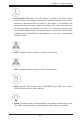
Remove any packaging from the chassis. If the rear fans (set of two fans 4.
nearest the I/O slots) or the air shroud is in place, remove them.
If required by your motherboard, install standoffs in any areas that do not 5.
have a permanent standoff. To do this, tighten a hexagonal optional standoff
into the chassis.
Lay the motherboard on the chassis aligning the permanent and optional 6.
standoffs.
Secure the motherboard to the chassis using the rounded, Phillips head 7.
screws. Do not exceed eight pounds of torque per square inch when tighten-
ing down the motherboard.
Secure the CPU(s) and heatsinks to the motherboard.8.
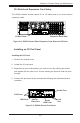
Power Supply Cables
Name Number
Connects
to:
Description
20-pin or 24-pin
power cable
1
Mother-
board
20-pin or 24-pin power cable provides
electricity to the motherboard. Has 20 -
24 yellow, black, gray, red, orange, green
and blue wires.
HDD (Hard
Drive) power
cable
3 Backplane
Each cable has 3 connectors (two Hard
Drive [HDD] Attach the HDD connectors
to the backplane. .
8-pin mother-
board cable
1
Mother-
board
Provides power to the motherboard CPU.
This cable has 2 black and 2 yellow
wires.
4-pin mother-
board cable
1
Mother-
board
Provides power to PCI expansion card.
This cable has 2 black and 2 yellow
wires.
5-pin SMBus
power cable
(small)
1
Mother-
board
Allows the SM (System Management)
Bus to monitor power supply
2-pin INT cable 1
Mother-
board
Intrusion detection cable allows the sys-
tem to log when the server chassis has
been opened.
Power Supply Connections
Connect each of the following cables, as required, by your motherboard manufac-
turer. In some instances, some cables may not need to be connected.