
User`s manual

E-5
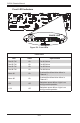
Appendix E: BPN-SAS-836A Backplane Specications
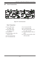
Backplane
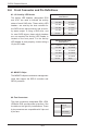
Main Power
4-Pin Connector
Pin# Denition
1 +12V
2 and 3
Ground
4 +5V
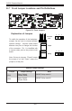
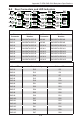
#9. Backplane Main Power Connectors
The 4-pin connectors, designated JP10,
JP13, JP46, and JP48, provide power to the
backplane. See the table on the right for pin
denitions. All four of these connectors must
be used at the same time.
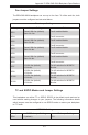
#5., #6., #7., #8. I
2
C Connectors
The I
2
C connectors, designated JP37, JP52,
JP95, and JP96, are for enclosure manage-
ment of the I
2
C mode connection. See the
table on the right for pin denitions.
I
2
C Y-Cable
Connector
Pin Denitions
Pin# Denition
1 Data
2 Ground
3 Clock
4 No Connection
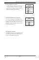
#10. Upgrade Connectors
The upgrade connectors are designated JP69
(for U19) and JP78 (for U40). Upgrade connec-
tors are for manufacturing use only.