SUPER M14T Mobile Rack USER'S GUIDE Rev. 1.
M14T Mobile Rack User's Guide The information in this User’s Manual has been carefully reviewed and is believed to be accurate. The vendor assumes no responsibility for any inaccuracies that may be contained in this document, makes no commitment to update or to keep current the information in this manual, or to notify any person or organization of the updates. Please Note: For the most up-to-date version of this manual, please see our web site at www.supermicro.com. Super Micro Computer, Inc.
Safety Information and Technical Specifications Table of Contents Chapter 1 Introduction 1-1 Overview ......................................................................................................... 1-1 1-2 Product Features ........................................................................................... 1-1 Operating Systems Supported ........................................................................ 1-2 System Monitoring ........................................................
Safety Information and Technical Specifications Chapter 1 Introduction 1-1 Overview This manual is written for system integrators, PC technicians and knowledgeable PC users who intend to integrate Supermicro's intelligent, highly expandable and costeffective mobile rack solutions into their systems. It provides the user with detailed information for the installation and use of the M14T mobile rack. The Supermicro M14T mobile rack, supports up to four hot-swappable SAS/SATA hard drives.
M14T Mobile Rack User's Guide Operating Systems Supported For the most up-to-date information visit the Supermicro Web site at www.supermicro.
Safety Information and Technical Specifications 1-4 Contacting Supermicro Headquarters Address: Super Micro Computer, Inc. 980 Rock Ave. San Jose, CA 95131 U.S.A. Tel: +1 (408) 503-8000 Fax: +1 (408) 503-8008 Email: marketing@supermicro.com (General Information) support@supermicro.com (Technical Support) Web Site: www.supermicro.com Europe Address: Super Micro Computer B.V.
M14T Mobile Rack User's Guide 1-5 Returning Merchandise for Service A receipt or copy of your invoice marked with the date of purchase is required before any warranty service will be rendered. You can obtain service by calling your vendor for a Returned Merchandise Authorization (RMA) number. When returning to the manufacturer, the RMA number should be prominently displayed on the outside of the shipping carton, and mailed prepaid or hand-carried.
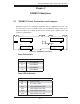
Safety Information and Technical Specifications Chapter 2 SASM14V Backplane 2-1 SASM14V Front Connectors and Jumpers Backplane layout: The following information reflects SASM14V Revision 1.0, the most current release available at the time of publication. Always refer to the Supermicro Web site at www.supermicro.com for the latests updates, parts and supported configurations.
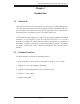
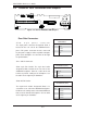
M14T Mobile Rack User's Guide 2-2 SASM14V Rear Connectors and Jumpers JP26 JP42 JP22 1 1 ACT In Fan J11 1 SAS In +5V GND GND +12V 4-Pin PWR JP10 JP25 JP18 Figure 2-2: Rear Connectors and Jumpers Rear Side Connectors 4-pin Power Connector Pin Definitions JP10: 4-pin power connector The 4-pin power connector designated JP10, is located on the rear side of the SASM14V backplane. This power connector must be connected to your power supply in order to provide adequate power to the backplane.
Safety Information and Technical Specifications Rear Jumpers Description Definition Open (*Default) Normal Closed Buzzer reset Open Set overheat temperature to 45º Celcius Pins 1-2 (*Default) Set overheat temperature to 50º Celcius Pins 2-3 Set overheat temperature to 55º Celcius Open Fan disabled Closed (*Default) Fan disabled 2-3
Safety Information and Technical Specifications Chapter 3 Installation Instructions 3-1 Packing List Examine the following items that are included in your shipping package. If any items are missing or damaged, please contact your retailer immediately. • One 4-drive mobile rack cage (CSE-M14 ((B)) P) • Four hot-swappable 2.
M14T Mobile Rack User's Guide Before Accessing the Mobile Rack: 1. Turn off all peripheral devices and the power supply connected to the chassis and unplug all power cords from the system or the wall outlets. 2. Disconnect all the cables and label the cables for easy identification. 3. Use a grounded wrist strap designed to prevent static discharge when handling components. 4. Save all the screws and fasteners for later use. (If necessary, label these screws or fasteners for easy identification.) 5.
Safety Information and Technical Specifications 3-4 Cooling Fan Installation and Removal If your M14T mobile rack is a stand-alone model, you will need to install the cooling fan onto the M14T before operating it. Installing the Cooling Fan 1. Place the cooling fan on the M14T mobile rack, aligning the mounting holes in the fan housing with the holes on the mobile rack. 2. Secure the fan to the mobile rack with two screws on each side of the fan. 3.
M14T Mobile Rack User's Guide 3-5 HDD Installation Removing the HDD Tray Before installing the hard disk into the M14T, you will need to remove the HDD drive trays from the cage. Removing the HDD Tray 1. Press the release tab toward the right to release the HDD drive tray from the M14T cage. 2. Once the drive tray is unlocked, pull it out using the handle.
Safety Information and Technical Specifications Installing the Hard Disk Drive into the Drive Tray Installing a Hard Disk Drive into the Drive Tray 1. Place a 2.5" HDD on top of the drive tray. 2. Align the HDD against the drive tray. 3. Secure the HDD onto the drive tray with four M-3 screws as shown below.
M14T Mobile Rack User's Guide Installing Hard Disk Drive Trays into the Mobile Rack Installing Drive Trays 1. After you've installed a hard disk drive into a drive tray as described on the previous page, you are ready to install the HDD into the mobile rack. Insert a loaded hard drive tray into a drive bay. Figure 3-6: The M14T Mobile Rack 2. Push the HDD inward until it is fully seated in the drive bay. 3. Press the handle inward toward the mobile rack, pressing it into the locking position.
Safety Information and Technical Specifications 3-6 Rear Panel Removal and Installation (Optional) Removing the Rear Panel 1. Follow the procedures given previously to remove the cooling fan from the M14T mobile rack. 2. After the cooling fan is detached, remove the four screws from the M14T as shown below. 12 13 Figure 3-8: Removing the Rear Panel 3. Once the screws are removed, pull the rear panel away from the M14T to remove it.
M14T Mobile Rack User's Guide Disclaimer (cont.) The products sold by Supermicro are not intended for and will not be used in life support systems, medical equipment, nuclear facilities or systems, aircraft, aircraft devices, aircraft/emergency communication devices or other critical systems whose failure to perform be reasonably expected to result in significant injury or loss of life or catastrophic property damage.