
User`s manual

Chapter 2: Installation
2-21
B
A
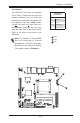
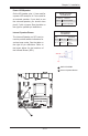
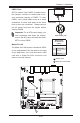
Power LED/Speaker
On the JD1 header, pins 1~3 are used for
a power LED and pins 4~7 are used for
an external speaker. If you wish to use
the onboard speaker, you should close
pins 6-7 with a jumper. See the table on
the right for speaker pin denitions.
Speaker Connector
PinDenitions
Pin Setting Denition
Pins 6-7 Internal Speaker
Pins 4-7 External Speaker
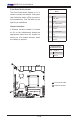
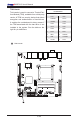
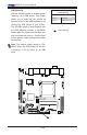
Internal Speaker/Buzzer
The Internal Speaker on SP1 can be
used to provide audible indications for
various beep codes. See the table on
the right for pin denitions. Refer to
the layout below for the locations of
the Internal Buzzer (SP1).
Internal Buzzer
PinDenition
Pin# Denitions
Pin 1 Pos. (+) Beep In
Pin 2 Neg. (-) Alarm
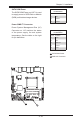
Speaker
PWR LED/SPKR
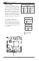
Internal Speaker/Buzzer
A
B