
User`s manual


1-6
X9DRX+-F Motherboard User’s Manual
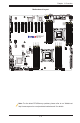
Warning!
To provide adequate power supply to the motherboard, be sure to connect
the 24-pin PWR (JPW1), the 8-pin PWR connectors (JPW2, JPW3), and
the 4-pin PWR connector (JPW4) to the power supply. Failure to do so will
void the manufacturer warranty on your power supply and motherboard.
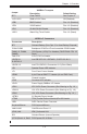
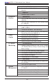
(CPU2)Slots5~7, Slots
9~10
PCI-Express 3.0 x8 Slots
(CPU2) Slot11 PCI-Express 2.0 x4 in x8 Slot
3-SGPIO 1/2/3 Serial_Link General Purpose I/O Headers
BP USB 0/1, 2/3 Back Panel USB 0/1, 2/3
USB 4, 5 Front Panel Type A USB Connections
USB 6/7, USB 8/9 Front Panel Accessible USB Connections
UID UID (Unit Identication) Switch
VGA Backpanel VGA Port
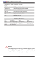
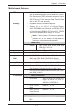
X9DRX+-F LED Indicators
LED Description State Status
LED1 BMC Heartbeat LED Green: Blinking BMC Normal
LED2 Onboard PWR LED Green: On Main Power On
LED3 UID Switch LED