X9DRX+-F USER’S MANUAL Revision 1.
The information in this User’s Manual has been carefully reviewed and is believed to be accurate. The vendor assumes no responsibility for any inaccuracies that may be contained in this document, and makes no commitment to update or to keep current the information in this manual, or to notify any person or organization of the updates. Please Note: For the most up-to-date version of this manual, please see our Website at www.supermicro.com. Super Micro Computer, Inc.
Preface Preface This manual is written for system integrators, PC technicians and knowledgeable PC users. It provides information for the installation and use of the X9DRX+-F motherboard. About This Motherboard The Super X9DRX+-F motherboard supports dual Intel E5-2600 Series (Socket R) processors that offer QPI (Intel QuickPath Interface) Technology (V.1.1), providing point-to-point connection with a transfer speed of up to 8.0 TG/s.
X9DRX+-F Motherboard User’s Manual Conventions Used in the Manual Pay special attention to the following symbols for proper system installation and to prevent damage to the system or injury to yourself: Danger/Caution: Instructions to be strictly followed to prevent catastrophic system failure or to avoid bodily injury Warning: Important information given to ensure proper system installation or to prevent damage to the components Note: Additional information given to differentiate between various models or
Preface Contacting Supermicro Headquarters Address: Super Micro Computer, Inc. 980 Rock Ave. San Jose, CA 95131 U.S.A. Tel: +1 (408) 503-8000 Fax: +1 (408) 503-8008 Email: marketing@supermicro.com (General Information) support@supermicro.com (Technical Support) Website: www.supermicro.com Europe Address: Super Micro Computer B.V. Het Sterrenbeeld 28, 5215 ML 's-Hertogenbosch, The Netherlands Tel: +31 (0) 73-6400390 Fax: +31 (0) 73-6416525 Email: sales@supermicro.
X9DRX+-F Motherboard User’s Manual Table of Contents Preface Chapter 1 Overview 1-1 Overview.......................................................................................................... 1-1 1-2 Processor and Chipset Overview...................................................................1-11 1-3 Special Features............................................................................................ 1-12 1-4 PC Health Monitoring.....................................................
Table of Contents Power LED ............................................................................................... 2-20 HDD LED................................................................................................... 2-21 NIC1/NIC2 LED Indicators........................................................................ 2-21 Overheat (OH)/Fan Fail/PWR Fail/UID LED............................................. 2-22 Power Fail LED.................................................................
X9DRX+-F Motherboard User’s Manual No Video.......................................................................................................... 3-2 System Boot Failure ...................................................................................... 3-2 Losing the System’s Setup Configuration........................................................ 3-2 Memory Errors ................................................................................................
Chapter 1: Overview Chapter 1 Overview 1-1 Overview Checklist Congratulations on purchasing your computer motherboard from an acknowledged leader in the industry. Supermicro boards are designed with the utmost attention to detail to provide you with the highest standards in quality and performance. Please check that the following items have all been included with your motherboard. If anything listed here is damaged or missing, contact your retailer. The following items are included in the retail box.
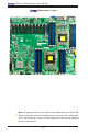
X9DRX+-F Motherboard User’s Manual Motherboard Image Note: All graphics shown in this manual were based upon the latest PCB Revision available at the time of publishing of the manual. The motherboard you've received may or may not look exactly the same as the graphics shown in this manual.
Chapter 1: Overview Motherboard Layout P1-DIMMA1 P1-DIMMB1 P1-DIMMA2 P1-DIMMB2 JPI2C1 JPW2 JTPM1 TPM/PORT80 I-SATA1 I-SATA3 I-SATA5 JPW1 USB6/7 USB8/9 S-SATA3 S-SATA1 S-SATA2 S-SATA0 3-SPGPIO3 3-SPGPIO2 JL1 FANB JPT1 JF1 FAN1 FANA FAN2 FAN7/CPU1 JBT1 I-SATA4 I-SATA0 JSD1 3-SPGPIO1 I-SATA2 FAN/PCH JPW3 FAN8/CPU2 CPLD JPW4 P2-DIMMG1 P2-DIMMG2 P2-DIMMH1 P2-DIMMH2 P2-DIMMF2 P2-DIMMF1 P2-DIMME2 P2-DIMME1 USB5 JITP2 FAN3 FAN4 FAN5 CPU2 Slot 11 PCI-E 2.
X9DRX+-F Motherboard User’s Manual X9DRX+-F Quick Reference FAN4 P2-DIMMG1 P2-DIMMG2 P2-DIMMH1 P2-DIMMH2 P2-DIMMF2 P2-DIMMF1 P2-DIMME2 P2-DIMME1 P1-DIMMA1 P1-DIMMB1 P1-DIMMA2 P1-DIMMB2 JPI2C1 JPW2 JTPM1 TPM/PORT80 I-SATA1 I-SATA3 I-SATA5 CPLD JPW1 USB6/7 USB8/9 S-SATA3 S-SATA1 S-SATA2 S-SATA0 3-SPGPIO3 3-SPGPIO2 JL1 FANB JPT1 JF1 FAN1 FANA FAN2 FAN7/CPU1 JBT1 I-SATA4 I-SATA0 JSD1 3-SPGPIO1 I-SATA2 FAN/PCH JPW3 FAN8/CPU2 USB5 JITP2 JPW4 FAN5 CPU2 Slot 11 PCI-E 2.
Chapter 1: Overview X9DRX+-F Jumpers Jumper Description Default Setting JBT1 Clear CMOS See Chapter 3 JI2C1/JI2C2 SMB to PCI-E Slots Off (Disabled) JPB1 BMC Enabled Pins 1-2 (Enabled) JPG1 VGA Enabled Pins 1-2 (Enabled) JPL1 GLAN1/GLAN2 Enable Pins 1-2 (Enabled) JWD1 Watch Dog Timer Enable Pins 1-2 (Reset) X9DRX+-F Connectors Connectors Description BT1 Onboard Battery (See Chpt.
X9DRX+-F Motherboard User’s Manual (CPU2)Slots5~7, Slots 9~10 PCI-Express 3.0 x8 Slots (CPU2) Slot11 PCI-Express 2.
Chapter 1: Overview Motherboard Features CPU • Dual Intel® E5-2600 Series (Socket R) processors; each processor supports four full-width Intel QuickPath Interconnect (QPI) links (with support of up to 25.6 GT/s per QPI link and with Data Transfer Rate of up to 8.
X9DRX+-F Motherboard User’s Manual Serial (COM) Port • Two (2) Fast UART 16550 Connection: 9-pin RS232 port Super I/O • Peripheral Devices BIOS Power Config. USB Devices • Four (4) USB ports on the rear I/O panel (USB 0/1, USB 2/3), • Four (4) USB connections for front access (USB 6/7, USB 8/9), • Two (2) Type A USB connection for front access (USB 4, USB 5) • • 128 Mb SPI AMI BIOS® SM Flash BIOS • • • • ACPI/ACPM Power Management • Onboard voltage monitors for 1.8V, +3.3V, 3.
Chapter 1: Overview Dimensions • 15.20" (L) x 13.20" (W) (386.08 mm x 335.28 mm) Note: For IPMI Configuration Instructions, please refer to the Embedded IPMI Configuration User's Guide available @ http://www.supermicro.com/ support/manuals/.
X9DRX+-F Motherboard User’s Manual #1 #2 #1 #2 A BIOS SPI Flash SPI DMI PEG [0..3] SATA [0..5] SATA Gen2 3GB/s SSB PET [1..7] Intel C602 SATA Gen2 [0..3] PCI USB [10,11] LPC DDR2 RAM ports 0,1 2,3 USB [0..
Chapter 1: Overview 1-2 Processor and Chipset Overview Built upon the functionality and the capability of Intel E5-2600 Series (Socket R) processors and the C602 chipset, the X9DRX+-F motherboard provides the performance and feature sets required for dual_processor-based HPC/Cluster/ Database servers. With support of Intel QuickPath interconnect (QPI) Technology, the X9DRX+-F offers point-to-point serial interconnect interface with a transfer speed of up to 8.0 GT/s, providing superb system performance.
X9DRX+-F Motherboard User’s Manual 1-3 Special Features Recovery from AC Power Loss The Basic I/O System (BIOS) provides a setting that determines how the system will respond when AC power is lost and then restored to the system. You can choose for the system to remain powered off (in which case you must press the power switch to turn it back on), or for it to automatically return to the power-on state. See the Advanced BIOS Setup section for this setting. The default setting is Last State.
Chapter 1: Overview the user of certain system events. For example, you can configure SuperDoctor to provide you with warnings when the system temperature, CPU temperatures, voltages, and fan speeds go beyond a predefined range. 1-5 ACPI Features ACPI stands for Advanced Configuration and Power Interface.
X9DRX+-F Motherboard User’s Manual It must also be SSI compliant. (For more information, please refer to the Website at http://www.ssiforum.org/). Additionally, in areas where noisy power transmission is present, you may choose to install a line filter to shield the computer from noise. It is recommended that you also install a power surge protector to help avoid problems caused by power surges.
Chapter 1: Overview Manageability Engine (ME) The Manageability Engine, which is an ARC controller embedded in the PCH, provides Server Platform Services (SPS) to your system. The services provided by SPS are different from those provided by the ME on client platforms.
X9DRX+-F Motherboard User’s Manual • Provides remote Hardware Health Monitoring via IPMI. Key features • Provides Network Management Security via remote access/console redirection. • • Supports the following Management tools: IPMIView, CLI (Command Line Interface) RMCP+ protocol supported Note 1: For more information on IPMI configuration, please refer to the IPMI User's Guide posted on our website at http://www.supermicro.com/ support/manuals/.
Chapter 2: Installation Chapter 2 Installation 2-1 Static-Sensitive Devices Electrostatic Discharge (ESD) can damage electronic components. To avoid damaging your system board, it is important to handle it very carefully. The following measures are generally sufficient to protect your equipment from ESD. • • • • • • Precautions Use a grounded wrist strap designed to prevent static discharge. Touch a grounded metal object before removing the board from the antistatic bag.
X9DRX+-F Motherboard User’s Manual 2-2 Processor and Heatsink Installation ! Warning: When handling the processor package, avoid placing direct pressure on the label area. Notes: Always connect the power cord last, and always remove it before adding, removing or changing any hardware components. Make sure that you install the processor into the CPU socket before you install the CPU heatsink. If you buy a CPU separately, make sure that you use an Intel-certified multi-directional heatsink only.
Chapter 2: Installation 2. Press the second load lever labeled 'Close 1st' to release the load plate that covers the CPU socket from its locking position. 1 Press down on Load the Lever labeled 'Close 1st' NI EN Pull lever away from the socket WA R WA R OP 2 NG NI NG ! OP EN 1st ! 1st 3. With the lever labeled 'Close 1st' fully retracted, gently push down on the 'Open 1st' lever to open the load plate. Lift the load plate to open it completely. Gently push down to pop the load plate open.
X9DRX+-F Motherboard User’s Manual 1. Using your thumb and the index finger, remove the 'WARNING' plastic cap from the socket. WA R NIN G! 2. Use your thumb and index finger to hold the CPU on its edges. Align the CPU keys, which are semi-circle cutouts, against the socket keys. Socket Keys CPU Keys 3. Once they are aligned, carefully lower the CPU straight down into the socket. (Do not drop the CPU on the socket. Do not move the CPU horizontally or vertically.
Chapter 2: Installation 4. With the CPU inside the socket, inspect the four corners of the CPU to make sure that the CPU is properly installed. 5. Close the load plate with the CPU inside the socket. Lock the lever labeled 'Close 1st' first, then lock the lever labeled 'Open 1st' second. Use your thumb to gently push the load levers down to the lever locks. 1 2 Push down and lock the level labeled 'Close 1st'. Gently close the load plate.
X9DRX+-F Motherboard User’s Manual Installing a Passive CPU Heatsink 1. Do not apply any thermal grease to the heatsink or the CPU die -- the required amount has already been applied. 2. Place the heatsink on top of the CPU so that the four mounting holes are aligned with those on the Motherboard's and the Heatsink Bracket underneath. 3. Screw in two diagonal screws (i.e., the #1 and the #2 screws) until just snug (-do not over-tighten the screws to avoid possible damage to the CPU.) 4.
Chapter 2: Installation Removing the Heatsink ! Warning: We do not recommend that the CPU or the heatsink be removed. However, if you do need to uninstall the heatsink, please follow the instructions below to avoid damaging the CPU or the CPU socket. 1. Unscrew the heatsink screws from the motherboard in the sequence as shown in the illustration below. 2. Gently wriggle the heatsink to loosen it from the CPU. (Do not use excessive force when wriggling the heatsink!) 3.
X9DRX+-F Motherboard User’s Manual 2-3 Installing and Removing the Memory Modules Note: Check Supermicro's Website for recommended memory modules. CAUTION Exercise extreme care when installing or removing DIMM modules to prevent any possible damage. Installing & Removing DIMMs 1. Insert the desired number of DIMMs into the memory slots, starting with P1DIMM #1A. (For best performance, please use the memory modules of the same type and speed.) 2.
Chapter 2: Installation Memory Support for the X9DRX+-F Motherboard The X9DRX+-F Motherboard supports up to 512 GB of DDR3 Registered/Load Reduced ECC or Unbuffered ECC/Non-ECC 1600/1333/1066/800 MHz memory modules in 16 DIMM slots. For the latest memory updates, please refer to our website a at http://www.supermicro.com/products/motherboard. Processor & Memory Module Population Configuration For memory to work properly, follow the tables below for memory population.
X9DRX+-F Motherboard User’s Manual Intel E5-2600 Series Processor UDIMM Memory Support Ranks Per DIMM & Data Width Memory Capacity Per DIMM Speed (MT/s) and Voltage Validated by Slot per Channel (SPC) and DIMM Per Channel (DPC) (See the Note below) 1 Slot Per Channel 1DPC 2 Slots Per Channel 1DPC 2DPC 1.35V 1.5V 1.35V 1.5V 1.35V 1.
Chapter 2: Installation Intel E5-2600 Series Processor LRDIMM Memory Support Ranks Per DIMM & Data Width Memory Capacity Per DIMM (See the Note Below) Speed (MT/s) and Voltage Validated by Slot per Channel (SPC) and DIMM Per Channel (DPC) 1 Slot Per Channel 2 Slots Per Channel 1DPC 1DPC and 2DPC 1.35V 1.5V 1.35V 1.
X9DRX+-F Motherboard User’s Manual 2-4 Motherboard Installation All motherboards have standard mounting holes to fit different types of chassis. Make sure that the locations of all the mounting holes for both motherboard and chassis match. Although a chassis may have both plastic and metal mounting fasteners, metal ones are highly recommended because they ground the motherboard to the chassis. Make sure that the metal standoffs click in or are screwed in tightly.
Chapter 2: Installation Installing the Motherboard 1. Install the I/O shield into the chassis. 2. Locate the mounting holes on the motherboard. 3. Locate the matching mounting holes on the chassis. Align the mounting holes on the motherboard against the mounting holes on the chassis. 4. Install standoffs in the chassis as needed. 5. Install the motherboard into the chassis carefully to avoid damaging motherboard components. 6.
X9DRX+-F Motherboard User’s Manual Control Panel Connectors and I/O Ports 2-5 The I/O ports are color coded in conformance with the PC 99 specification. See the picture below for the colors and locations of the various I/O ports.
COM2 FAN4 Serial Ports P2-DIMMG1 P2-DIMMG2 P2-DIMMH1 P2-DIMMH2 P2-DIMMF2 P2-DIMMF1 P2-DIMME2 P2-DIMME1 P1-DIMMA1 P1-DIMMB2 P1-DIMMB1 P1-DIMMA2 P1-DIMMD2 P1-DIMMD1 P1-DIMMC1 P1-DIMMC2 JPW3 FAN8/CPU2 USB4 JVRM_I2C1 JVRM_I2C2 Clock Chip JSTBY1 JPI2C1 USB5 JPW2 JTPM1 TPM/PORT80 I-SATA1 I-SATA3 I-SATA5 JPW1 3-SPGPIO2 JL1 FANB JPT1 JF1 FAN1 FANA FAN2 FAN7/CPU1 JBT1 USB6/7 USB8/9 S-SATA3 S-SATA2 S-SATA1 S-SATA0 3-SPGPIO3 I-SATA0 JSD1 3-SPGPIO1 I-SATA2 I-SATA4 2-15 1 D
X9DRX+-F Motherboard User’s Manual Universal Serial Bus (USB) Four Universal Serial Bus ports (USB 0/1, USB 2/3) are located on the I/O back panel. Please note that BP USB 2/3 can also be used for Keyboard/ Mouse connections. In addition, three USB headers, located close to the IO Hub, provides four front-accessible USB connections (USB USB 6/7, USB 8/9). Two Type A connectors (USB4, USB5) also supports front panel USB connections. (Cables are not included). See the tables on the right for pin definitions.
Chapter 2: Installation Ethernet Ports Two Gigabit Ethernet ports (LAN1, LAN2) are located on the I/O backplane on the motherboard. In addition, an IPMI_Dedicated LAN is located above USB 0/1 ports on the backplane to provide KVM support for IPMI 2.0. All these ports accept RJ45 type cables. Please refer to the LED Indicator Section for LAN LED information.
X9DRX+-F Motherboard User’s Manual Unit Identifier Switch A Unit Identifier (UID) Switch and two LED Indicators are located on the motherboard. The UID Switch is located next to the LAN ports on the backplane. The Rear UID LED (LED3) is located next to the UID Switch. The Front Panel UID LED is located at Pins 7/8 of the Front Control Panel at JF1. Connect a cable to Pin 8 on JF1 for Front Panel UID LED indication.
Chapter 2: Installation Front Control Panel JF1 contains header pins for various buttons and indicators that are normally located on a control panel at the front of the chassis. These connectors are designed specifically for use with Supermicro's server chassis. See the figure below for the descriptions of the various control panel buttons and LED indicators. Refer to the following section for descriptions and pin definitions.
X9DRX+-F Motherboard User’s Manual Front Control Panel Pin Definitions NMI Button NMI Button Pin Definitions (JF1) The non-maskable interrupt button header is located on pins 19 and 20 of JF1. Refer to the table on the right for pin definitions. Power LED Pin# Definition 19 Control 20 Ground Power LED Pin Definitions (JF1) The Power LED connection is located on pins 15 and 16 of JF1. Refer to the table on the right for pin definitions. Pin# Definition 15 3.3V 16 PWR LED A. NMI B.
Chapter 2: Installation HDD LED HDD LED Pin Definitions (JF1) The HDD LED connection is located on pins 13 and 14 of JF1. Attach a cable here to indicate HDD activity. See the table on the right for pin definitions. Pin# Definition 13 3.3V Standby 14 HD Active NIC1/NIC2 LED Indicators GLAN1/2 LED Pin Definitions (JF1) The NIC (Network Interface Controller) LED connection for GLAN port 1 is located on pins 11 and 12 of JF1, and the LED connection for GLAN Port 2 is on Pins 9 and 10.
X9DRX+-F Motherboard User’s Manual Overheat (OH)/Fan Fail/PWR Fail/ UID LED OH/Fan Fail/ PWR Fail/Blue_UID LED Pin Definitions (JF1) Connect an LED cable to pins 7 and Pin# 8 of Front Control Panel to use the Overheat/Fan Fail/Power Fail and UID LED connections. The Red LED on pin 7 provides warnings of overheat, fan failure or power failure. The Blue LED on pin 8 works as the front panel UID LED indicator. The Red LED takes precedence over the Blue LED by default.
Chapter 2: Installation Reset Button Reset Button Pin Definitions (JF1) The Reset Button connection is located on pins 3 and 4 of JF1. Attach it to a hardware reset switch on the computer case. Refer to the table on the right for pin definitions. Pin# Definition 3 Reset 4 Ground Power Button Power Button Pin Definitions (JF1) The Power Button connection is located on pins 1 and 2 of JF1. Momentarily contacting both pins will power on/off the system.
X9DRX+-F Motherboard User’s Manual 2-6 Connecting Cables ATX Power 24-pin Connector Pin Definitions Pin# Definition Pin # Definition Power Connectors 13 +3.3V 1 +3.3V A 24-pin main power supply connector (JPW1), two 8-pin CPU PWR connectors (JPW2/3), and a 4-pin PWR connector are located on the motherboard. These power connectors meet the SSI EPS 12V specification. These power connectors must also be connected to your power supply. See the table on the right for pin definitions. 14 -12V 2 +3.
Chapter 2: Installation Fan Headers Fan Header Pin Definitions This motherboard has ten system/CPU/ PCH fan headers (Fan 1~Fan 8 Fan A, and Fan B) on the motherboard. Fans 7/8 are CPU fans. All these 4-pin fans headers are backward compatible with the traditional 3-pin fans. The fan speeds are controlled by Thermal Management via Hardware Monitoring in the Advanced Setting in the BIOS for the 4-pin fans (See Chapter 5 for more details.
X9DRX+-F Motherboard User’s Manual Internal Speaker Internal Buzzer (SP1) Pin Definition The Internal Speaker, located at SP1, can be used to provide audible indica- Pin# tions for various beep codes. See the table on the right for pin definitions. Refer to the layout below for the locations of the Internal Buzzer (SP1). Pos. (+) Beep In Pin 2 Neg.
Chapter 2: Installation TPM Header/Port 80 Header TPM/Port 80 Header Pin Definitions A Trusted Platform Module/Port 80 header is located at JTPM1 to provide TPM support and Port 80 connection. Use this header to enhance system performance and data security. See the table on the right for pin definitions. Pin # Definition 2 GND 3 LFRAME# 4 <(KEY)> 5 LRESET# 6 +5V (X) 7 LAD 3 8 LAD 2 9 +3.
X9DRX+-F Motherboard User’s Manual 2 System Management Bus Header FAN4 P1-DIMMA1 P1-DIMMB2 P1-DIMMB1 P1-DIMMA2 JPW3 FAN8/CPU2 JPI2C1 JPW2 JTPM1 TPM/PORT80 I-SATA1 I-SATA3 I-SATA5 JPW1 S-SATA1 JL1 FANB JPT1 JF1 FAN1 FANA FAN2 FAN7/CPU1 JBT1 USB6/7 USB8/9 S-SATA3 S-SATA2 S-SATA0 3-SPGPIO3 3-SPGPIO2 I-SATA0 JSD1 3-SPGPIO1 I-SATA2 I-SATA4 2-28 P2-DIMMG1 P2-DIMMG2 P2-DIMMH1 P2-DIMMH2 P2-DIMMF2 P2-DIMMF1 P2-DIMME2 P2-DIMME1 CPU2 Slot 11 PCI-E 2.
Chapter 2: Installation 3-SGPIO 1/2/3 Headers 3-SGPIO Pin Definitions Three SGPIO (Serial-Link General Purpose Input/Output) headers are located on the motherboard. These headers support Serial_Link interface for onboard SATA connections. See the table on the right for pin definitions.
X9DRX+-F Motherboard User’s Manual Standby Power The 3V Standby Power header is located at JSTBY1 on the motherboard. See the layout below for the location.
Chapter 2: Installation 2-7 Jumper Settings Explanation of Jumpers 3 2 1 3 2 1 Connector Pins To modify the operation of the motherboard, jumpers can be used to choose between optional settings. Jumpers create shorts between two pins to change the function of the connector. Pin 1 is identified with a square solder pad on the printed circuit board. See the motherboard layout pages for jumper locations.
X9DRX+-F Motherboard User’s Manual CMOS Clear JBT1 is used to clear CMOS. Instead of pins, this "jumper" consists of contact pads to prevent accidental clearing of CMOS. To clear CMOS, use a metal object such as a small screwdriver to touch both pads at the same time to short the connection. Always remove the AC power cord from the system before clearing CMOS. Note 1. For an ATX power supply, you must completely shut down the system, remove the AC power cord, and then short JBT1 to clear CMOS. Note 2.
Chapter 2: Installation VGA Enable VGA Enable Jumper Settings Jumper JPG1 allows the user to enable the onboard VGA connector. The default Jumper Setting setting is 1-2 to enable the connection. See the table on the right for jumper settings. Enabled (Default) 2-3 Disabled BMC Enable BMC Enable Jumper Settings Jumper JPB1 allows you to enable the embedded Nutovon (Baseboard Management) Controller to provide IPMI 2.0/ KVM support on the motherboard. See the table on the right for jumper settings.
X9DRX+-F Motherboard User’s Manual FAN4 P1-DIMMA1 P1-DIMMB2 P1-DIMMB1 P1-DIMMA2 JPI2C1 JPW2 JTPM1 TPM/PORT80 I-SATA1 I-SATA3 I-SATA5 CPLD JPW1 USB6/7 USB8/9 S-SATA3 S-SATA1 S-SATA2 S-SATA0 3-SPGPIO3 3-SPGPIO2 JL1 FANB JPT1 JF1 FAN1 FANA FAN2 FAN7/CPU1 JBT1 I-SATA4 I-SATA0 JSD1 3-SPGPIO1 I-SATA2 FAN/PCH JPW3 FAN8/CPU2 USB5 2-34 P2-DIMMG1 P2-DIMMG2 P2-DIMMH1 P2-DIMMH2 P2-DIMMF2 P2-DIMMF1 P2-DIMME2 P2-DIMME1 CPU2 Slot 11 PCI-E 2.
Chapter 2: Installation 2-8 Onboard LED Indicators Link Speed LED GLAN LEDs There are two GLAN ports on the motherboard. Each Gigabit Ethernet LAN port has two LEDs. The Yellow LED on the right indicates connection and activity. The Link LED on the left side may be green, amber or off to indicate the speed of the connection. See the tables at right for more information.
X9DRX+-F Motherboard User’s Manual Onboard Power LED Onboard PWR LED Indicator LED Settings An Onboard Power LED is located at LED2 on the motherboard. When this LED is on, the system is on. Be sure to turn off the system and unplug the power cord before removing or installing components. See the tables at right for more information.
Chapter 2: Installation FAN4 P1-DIMMA1 P1-DIMMB2 P1-DIMMB1 P1-DIMMA2 JPI2C1 JPW2 JTPM1 TPM/PORT80 I-SATA1 I-SATA3 I-SATA5 JPW1 USB6/7 USB8/9 S-SATA3 S-SATA1 S-SATA2 S-SATA0 3-SPGPIO3 3-SPGPIO2 JL1 FANB JPT1 JF1 FAN1 FANA FAN2 FAN7/CPU1 JBT1 I-SATA4 I-SATA0 JSD1 3-SPGPIO1 I-SATA2 FAN/PCH JPW3 FAN8/CPU2 USB5 2-37 P2-DIMMG1 P2-DIMMG2 P2-DIMMH1 P2-DIMMH2 P2-DIMMF2 P2-DIMMF1 P2-DIMME2 P2-DIMME1 CPU2 Slot 11 PCI-E 2.
X9DRX+-F Motherboard User’s Manual 2-9 Serial ATA Connections Serial ATA Ports Serial ATA Pin Definitions There are ten Serial_ ATA ports on the motherboard. I-SATA0/1 support SATA 3.0 connections. S-SATA0~3 and I-SATA2~5 are SATA 2.0 ports. These ports provide serial-link signal connections, which are faster than the connections of Parallel ATA. See the table on the right for pin definitions.
Chapter 3: Troubleshooting Chapter 3 Troubleshooting 3-1 Troubleshooting Procedures Use the following procedures to troubleshoot your system. If you have followed all of the procedures below and still need assistance, refer to the ‘Technical Support Procedures’ and/or ‘Returning Merchandise for Service’ section(s) in this chapter. Note: Always disconnect the power cord before adding, changing or installing any hardware components. Before Power On 1.
X9DRX+-F Motherboard User’s Manual No Video 1. If the power is on, but you have no video, remove all the add-on cards and cables. 2. Use the speaker to determine if any beep codes exist. Refer to Appendix A for details on beep codes. System Boot Failure If the system does not display POST or does not respond after the power is turned on, check the following: 1. Check for any error beep from the motherboard speaker. • • If there is no error beep, try to turn on the system without DIMM modules installed.
Chapter 3: Troubleshooting Memory Errors When a No-Memory Beep Code is issued by the system, check the following: 1. Make sure that the memory modules are compatible with the system and that the DIMM modules are properly and fully installed. (For memory compatibility, refer to the Memory Compatibility Chart posted on our Website @ http://www. supermicro.com.) 2. Check if different speeds of DIMMs have been installed. It is strongly recommended that you use the same RAM speed for all DIMMs in the system. 3.
X9DRX+-F Motherboard User’s Manual 4. System cooling: Check system cooling to make sure that all heatsink fans, and CPU/system fans, etc., work properly. Check Hardware Monitoring settings in the BIOS to make sure that the CPU and System temperatures are within the normal range. Also check the front panel Overheat LED, and make sure that the Overheat LED is not on. 5. Adequate power supply: Make sure that the power supply provides adequate power to the system.
Chapter 3: Troubleshooting 3-2 Technical Support Procedures Before contacting Technical Support, please take the following steps. Also, please note that as a motherboard manufacturer, Supermicro also sells motherboards through its channels, so it is best to first check with your distributor or reseller for troubleshooting services. They should know of any possible problem(s) with the specific system configuration that was sold to you. 1.
X9DRX+-F Motherboard User’s Manual 3-3 Battery Removal and Installation Battery Removal To remove the onboard battery, follow the steps below: 1. Power off your system and unplug your power cable. 2. Locate the onboard battery as shown below. 3. Using a tool such as a pen or a small screwdriver, push the battery lock outwards to unlock it. Once unlocked, the battery will pop out from the holder. 4. Remove the battery.
Chapter 3: Troubleshooting 3-4 Frequently Asked Questions Question: What are the various types of memory that my motherboard can support? Answer: The motherboard supports Registered/Load Reduced ECC or Unbuffered ECC/Non-ECC DDR3 DIMM modules. To enhance memory performance, do not mix memory modules of different speeds and sizes. Please follow all memory installation instructions given on Section 2-3 in Chapter 2.
X9DRX+-F Motherboard User’s Manual 3-5 Returning Merchandise for Service A receipt or copy of your invoice marked with the date of purchase is required before any warranty service will be rendered. You can obtain service by calling your vendor for a Returned Merchandise Authorization (RMA) number. When returning the motherboard to the manufacturer, the RMA number should be prominently displayed on the outside of the shipping carton, and the shipping package is mailed prepaid or hand-carried.
Chapter 4: AMI BIOS Chapter 4 BIOS 4-1 Introduction This chapter describes the AMI BIOS Setup utility for the X9DRX+-F. It also provides the instructions on how to navigate the AMI BIOS Setup utility screens. The AMI ROM BIOS is stored in a Flash EEPROM and can be easily updated. Starting BIOS Setup Utility To enter the AMI BIOS Setup utility screens, press the key while the system is booting up. Note: In most cases, the key is used to invoke the AMI BIOS setup screen.
X9DRX+-F Motherboard User’s Manual How To Change the Configuration Data The configuration data that determines the system parameters may be changed by entering the AMI BIOS Setup utility. This Setup utility can be accessed by pressing at the appropriate time during system boot. Note: For AMI UEFI BIOS Recovery, please refer to the UEFI BIOS Recovery User Guide posted @http://www.supermicro.com/support/manuals/.
Chapter 4: AMI BIOS The AMI BIOS main menu displays the following information: System Date This item displays the system date in Day MM/DD/YY format (e.g. Wed 10/12/2011). System Time This item displays the system time in HH:MM:SS format (e.g. 15:32:52). Supermicro X9DRX+-F Version This item displays the SMC version of the BIOS ROM used in this system. Build Date This item displays the date that the BIOS Setup utility was built.
X9DRX+-F Motherboard User’s Manual 4-3 Advanced Setup Configurations Use the arrow keys to select Advanced Setup and press to access the following submenu items. Boot Features Quiet Boot This feature allows the user to select bootup screen display between POST messages and the OEM logo. Select Disabled to display the POST messages. Select Enabled to display the OEM logo instead of the normal POST messages. The options are Enabled and Disabled.
Chapter 4: AMI BIOS Interrupt 19 Capture Interrupt 19 is the software interrupt that handles the boot disk function. When this item is set to Enabled, the ROM BIOS of the host adaptors will "capture" Interrupt 19 at bootup and allow the drives that are attached to these host adaptors to function as bootable disks. If this item is set to Disabled, the ROM BIOS of the host adaptors will not capture Interrupt 19, and the drives attached to these adaptors will not function as bootable devices.
X9DRX+-F Motherboard User’s Manual • CPU Stepping • Maximum CPU Speed • Minimum CPU Speed • Processor Cores • Intel HT (Hyper-Threading) Technology • Intel VT-x Technology • Intel SMX Technology • L1 Data Cache • L1 Code Cache • L2 Cache • L3 Cache CPU Speed This item displays the speed of the CPU installed in Socket 1/Socket 2. 64-bit This item indicates if the CPU installed in Socket 1 or Socket 2 supports 64-bit technology.
Chapter 4: AMI BIOS Limit CPUID Maximum This feature allows the user to set the maximum CPU ID value. Enable this function to boot the legacy operating systems that cannot support processors with extended CPUID functions. The options are Enabled and Disabled (for the Windows OS).
X9DRX+-F Motherboard User’s Manual Intel® Virtualization Technology (Available when supported by the CPU) Select Enabled to support Intel Virtualization Technology, which will allow one platform to run multiple operating systems and applications in independent partitions, creating multiple "virtual" systems in one physical computer. The options are Enabled and Disabled. Note: If there is any change to this setting, you will need to power off and restart the system for the change to take effect.
Chapter 4: AMI BIOS CPU C6 Report (Available when Power Technology is set to Custom) Select Enabled to allow the BIOS to report the CPU C6 State (ACPI C3) to the operating system. During the CPU C6 State, the power to all cache is turned off. The options are Enabled and Disabled. CPU C7 Report (Available when Power Technology is set to Custom) Select Enabled to allow the BIOS to report the CPU C7 State (ACPI C3) to the operating system. CPU C7 State is a processor-specific low C-State.
X9DRX+-F Motherboard User’s Manual Short Duration Power Limit This item displays the time period during which short duration power is maintained. Chipset Configuration North Bridge This feature allows the user to configure the settings for the Intel North Bridge. Integrated IO Configuration Intel VT-d Select Enabled to enable Intel Virtualization Technology support for Direct I/O VT-d by reporting the I/O device assignments to the VWM (Virtual Working Memory) through the DMAR ACPI Tables.
Chapter 4: AMI BIOS CPU1 Slot 1 PCI-E 3.0 x8 Link Speed This feature allows the user to set the PCI-Exp bus speed for the slot specified above. The options are Gen1 (Generation 1), Gen2 and Gen3. CPU1 Slot 2 PCI-E 3.0 x8 Link Speed This feature allows the user to set the PCI-Exp bus speed for the slot specified above. The options are Gen1 (Generation 1), Gen2 and Gen3. CPU1 Slot 4 PCI-E 3.0 x8 Link Speed This feature allows the user to set the PCI-Exp bus speed for the slot specified above.
X9DRX+-F Motherboard User’s Manual DIMM Configuration This section displays the following DIMM information. Current Memory Mode This item displays the current memory mode. Current Memory Speed This item displays the current memory speed. Mirroring This item displays if memory mirroring is supported by the motherboard. Memory mirroring creates a duplicate copy of the data stored in the memory to enhance data security. Sparing This item displays if memory sparing is supported by the motherboard.
Chapter 4: AMI BIOS Channel Interleaving This feature selects from the different channel interleaving methods. The options are Auto, 1 Way, 2 Way, 3, Way, and 4 Way. Rank Interleaving This feature allows the user to select a rank memory interleaving method. The options are Auto, 1 Way, 2 Way, 4, Way, and 8 Way. Patrol Scrub Patrol Scrubbing is a process that allows the CPU to correct correctable memory errors detected on a memory module and send the correction to the requestor (the original source).
X9DRX+-F Motherboard User’s Manual South Bridge Configuration This feature allows the user to configure the settings for the Intel PCH chip. PCH Information This feature displays the following PCH information. Name: This item displays the name of the PCH chip. Stepping: This item displays the status of the PCH stepping. USB Devices: This item displays the USB devices detected by the BIOS. All USB Devices This feature enables all USB ports/devices. The options are Disabled and Enabled.
Chapter 4: AMI BIOS SATA Configuration When this submenu is selected, the AMI BIOS automatically detects the presence of IDE or SATA devices and displays the following items. SATA Port0~SATA Port5: The AMI BIOS displays the status of each SATA port as detected by the BIOS. SATA Mode Use this feature to configure SATA mode for a selected SATA port. The options are Disabled, IDE Mode, AHCI Mode and RAID Mode.
X9DRX+-F Motherboard User’s Manual RAID Mode The following items are displayed when RAID Mode is selected: Port 0~5 Hot Plug Select Enabled to enable hot-plug support for the particular port. The options are Enabled and Disabled. SCU (Storage Control Unit) Configuration Storage Controller Unit Select Enabled to enable PCH SCU storage devices. The options are Disabled and Enabled. OnChip SCU Option ROM Select Enabled to support the onboard SCU Option ROM to boot up the system via a storage device.
Chapter 4: AMI BIOS SERR# Generation Select Enabled to allow a PCI device to generate an SERR number for a PCI Bus Signal Error Event. The options are Enabled and Disabled. Maximum Payload Select Auto to allow the system BIOS to automatically set the maximum payload value for a PCI-E device to enhance system performance. The options are Auto, 128 Bytes and 256 Bytes.
X9DRX+-F Motherboard User’s Manual Load Onboard SAS Option ROM Select Enabled to use the SAS Option ROM to boot the computer using a network device. The options are Enabled and Disabled. VGA Priority This feature allows the user to select the graphics adapter to be used as the primary boot device. The options are Onboard, and Offboard. Network Stack Select Enabled enable PXE (Preboot Execution Environment) or UEFI (Unified Extensible Firmware Interface) for network stack support.
Chapter 4: AMI BIOS Device Settings This item displays the settings of Serial Port 2. Change Settings Use this feature to set the optimal Environment Control Interface (PECI) setting for a serial port specified. The default setting is Auto, which will allow the AMI BIOS to automatically select the best setting for the PECI platform. Device Mode Use this feature to select the desired mode for a serial port specified. The options are Normal and High Speed.
X9DRX+-F Motherboard User’s Manual Bits Per second Use this feature to set the transmission speed for a serial port used in Console Redirection. Make sure that the same speed is used in the host computer and the client computer. A lower transmission speed may be required for long and busy lines. The options are 9600, 19200, 38400, 57600 and 115200 (bits per second). Data Bits Use this feature to set the data transmission size for Console Redirection. The options are 7 Bits and 8 Bits.
Chapter 4: AMI BIOS Legacy OS Redirection Resolution Use this feature to select the number of rows and columns used in Console Redirection for legacy OS support. The options are 80x24 and 80x25. Putty KeyPad This feature selects Function Keys and KeyPad settings for Putty, which is a terminal emulator designed for the Windows OS. The options are VT100, LINUX, XTERMR6, SC0, ESCN, and VT400.
X9DRX+-F Motherboard User’s Manual Flow Control This feature allows the user to set the flow control for Console Redirection to prevent data loss caused by buffer overflow. Send a "Stop" signal to stop sending data when the receiving buffer is full. Send a "Start" signal to start sending data when the receiving buffer is empty. The options are None, Hardware RTS/ CTS, and Software Xon/Xoff.
Chapter 4: AMI BIOS Pending Operation: This item displays the status of a pending operation. Current Status Information: This item displays the information regarding the current TPM status. TPM Enable Status This item displays the status of TPM Support to indicate if TPM is currently enabled or disabled. TPM Active Status This item displays the status of TPM Support to indicate if TPM is currently active or deactivated. TPM Owner Status This item displays the status of TPM Ownership.
X9DRX+-F Motherboard User’s Manual Intel ME Subsystem Configuration This feature displays the following ME Subsystem Configuration settings. • ME BIOS Interface Version • ME Version iSCSI Configuration: This item displays iSCSI configuration information: iSCSI Initiator Name: This item displays the name of the iSCSI Initiator, which is a unique name used in the world. Intel® I350 Gigabit Network Connections: These items display the following information on the Intel I350 LAN connections.
Chapter 4: AMI BIOS 4-4 • Factory MAC Address • Alternate MAC Address Event Logs Use this feature to configure Event Log settings. Change SMBIOS Event Log Settings This feature allows the user to configure SMBIOS Event settings. Enabling/Disabling Options SMBIOS Event Log Select Enabled to enable SMBIOS (System Management BIOS) Event Logging during system boot. The options are Enabled and Disabled. Runtime Error Logging Support Select Enabled to support Runtime Error Logging.
X9DRX+-F Motherboard User’s Manual PCI Error Logging Support Select Enabled to support error event logging for PCI slots. The options are Enabled and Disabled. Erasing Settings Erase Event Log Select Enabled to erase the SMBIOS (System Management BIOS) Event Log, which is completed before a event logging is initialized upon system reboot. The options are No and Yes. When Log is Full Select Erase Immediately to immediately erase SMBIOS error event logs that exceed the limit when the SMBIOS event log is full.
Chapter 4: AMI BIOS 4-5 IPMI Use this feature to configure Intelligent Platform Management Interface (IPMI) settings. IPMI Firmware Revision This item indicates the IPMI firmware revision used in your system. IPMI Status This item indicates the status of the IPMI firmware installed in your system. System Event Log Enabling/Disabling Options SEL Components Select Enabled for all system event logging at bootup. The options are Enabled and Disabled.
X9DRX+-F Motherboard User’s Manual When SEL is Full This feature allows the user to decide what the BIOS should do when the system event log is full. Select Erase Immediately to erase all events in the log when the system event log is full. The options are Do Nothing and Erase Immediately. Custom EFI Logging Options Log EFI Status Codes Select Enabled to log EFI (Extensible Firmware Interface) Status Codes, Error Codes or Progress Codes. The options are Enabled and Disabled.
Chapter 4: AMI BIOS Gateway IP Address This item displays the Gateway IP address for this computer. This should be in decimal and in dotted quad form (i.e., 192.168.10.253). 4-6 Boot This submenu allows the user to configure the following boot settings for the system. Boot Option Priorities Boot Option #1/ Boot Option #2/ Boot Option #3, etc. Use this feature to specify the sequence of boot device priority.
X9DRX+-F Motherboard User’s Manual 4-7 Security This menu allows the user to configure the following security settings for the system. Administrator Password Use this feature to set the Administrator Password which is required to enter the BIOS setup utility. The length of the password should be from 3 characters to 8 characters long. User Password Use this feature to set a User Password which is required to log into the system and to enter the BIOS setup utility.
Chapter 4: AMI BIOS 4-8 Save & Exit This submenu allows the user to configure the Save and Exit settings for the system. Discard Changes and Exit Select this option to quit the BIOS Setup without making any permanent changes to the system configuration, and reboot the computer. Select Discard Changes and Exit, and press .
X9DRX+-F Motherboard User’s Manual Discard Changes Select this feature and press to discard all the changes and return to the BIOS setup. When the dialog box appears, asking you if you want to load previous values, click Yes to load the values previous saved, or click No to keep the changes you've made so far. Restore Optimized Defaults Select this feature and press to load the optimized default settings that help optimize system performance.
Appendix A: BIOS POST Error Codes Appendix A BIOS Error Beep Codes During the POST (Power-On Self-Test) routines, which are performed at each system boot, errors may occur. Non-fatal errors are those which, in most cases, allow the system to continue to boot. The error messages normally appear on the screen. Fatal errors will not allow the system to continue with bootup procedure. If a fatal error occurs, you should consult with your system manufacturer for possible repairs.
X9DRX+-F Motherboard User’s Manual Notes A-2
Appendix B: Software Installation Instructions Appendix B Software Installation Instructions B-1 Installing Software Programs After you've installed the operating system, a screen as shown below will appear. You are ready to install software programs and drivers that have not yet been installed. To install these programs, click the icons to the right of these items. Note: To install the Windows OS, please refer to the instructions posted on our Website at http://www.supermicro.com/support/manuals/.
X9DRX+-F Motherboard User’s Manual B-2 Configuring SuperDoctor III The SuperDoctor III program is a Web-based management tool that supports remote management capability. It includes Remote and Local Management tools. The local management is called the SD III Client. The SuperDoctor III program included on the CDROM that came with your motherboard allows you to monitor the environment and operations of your system.
Appendix B: Software Installation Instructions SuperDoctor III Interface Display Screen-II (Remote Control) Note:The SDIII utility and the user guide can be downloaded from our website at: http://www.supermicro.com/products/accessories/software/ SuperDoctorIII.cfm. For Linux, we will still recommend that you use SuperDoctor II.
X9DRX+-F Motherboard User’s Manual Notes B-4
(Disclaimer Continued) The products sold by Supermicro are not intended for and will not be used in life support systems, medical equipment, nuclear facilities or systems, aircraft, aircraft devices, aircraft/emergency communication devices or other critical systems whose failure to perform be reasonably expected to result in significant injury or loss of life or catastrophic property damage.