
User`s manual
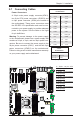

Chapter 2: Installation
2-29
JPME1
JI2C1
VGA1
I-SATA1
I-SATA0
I-SATA5
I-SATA4
I-SATA3
I-SATA2
JIPMB1
JPME2
JPL1
JBR1
JWD1
JPG1
JPB1
JVRM_I2C1
JVRM_I2C2
JVR1
FAN5
FAN6
FAN8
FAN7
FAN1
FAN2
FAN3
FAN4
JF2
T-SGPIO1
T-SGPIO2
JUSB6
JSD1
JBT1
JBAT1
JTPM1
JF1
JPI2C1
JOH1
JI2C2
JL1
JSTBY1
JUIDB
J4
JD1
LED3
LEDM1
LED2
LAN2/4
LAN1/3
CPU1
CPU2
CPU2
CPU1
CPU2
CPU1
PWR I2C
UID
P2-DIMME1
P2-DIMMF2
P2-DIMMF1
P2-DIMMG2
P2-DIMMG1
P2-DIMMH2
P2-DIMMH1
P1-DIMMA2
P1-DIMMA1
P1-DIMMB2
P1-DIMMB1
P1-DIMMC1
P1-DIMMC2
P1-DIMMD1
P1-DIMMD2
USB4/5USB8/9
SLOT1 PCI-E 3.0 X8
SLOT2 PCI-E 3.0 X8
SLOT3 PCI-E 3.0 X8
SLOT4 PCI-E 3.0 X8
SLOT5 PCI-E 3.0 X8
USB6
TPM/PORT80
BUZZER
CMOS CLEAR
SLOT6 PCI-E 3.0 X8
COM2
USB2/3
COM1
USB0/1
SP1
CPU2
IPMI_LAN
CPU2
CPU2
Battery
BIOS
JPW1
JPW2
24-Pin Main PWR
8-Pin PWR
JPW4
P2-DIMME2
JPW3
8-Pin PWR
4-Pin PWR
L-SAS4~7
L-SAS0~3
LSI SAS CTRL
Intel
PCH
JPS1
LAN
CTRL
BMC
CPU1
X9DRD-7LN4F
Rev. 1.02
KB/Mouse
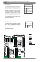
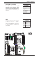
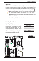
A. Internal Speaker
(Buzzer)
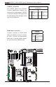
B. PWR LED/Speaker
Power LED/Speaker
On JD1 header, pins 1-3 are used for
power LED indication, and pins 4-7
are for the speaker. See the tables
on the right for pin denitions. Please
note that the speaker connector
pins (4-7) are used with an external
speaker. If you wish to use the on-
board speaker, you should close pins
6-7 with a jumper.
Speaker Connector
Pin Settings
Pin Setting Denition
Pins 4-7 External Speaker
Pins 6-7 Internal Speaker
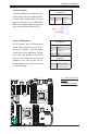
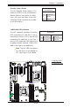
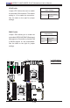
Internal Speaker
The Internal Speaker, located at SP1,
can be used to provide audible indica-
tions for various beep codes. See the
table on the right for pin denitions.
Refer to the layout below for the loca-
tions of the Internal Buzzer (SP1).
Internal Buzzer (SP1)
PinDenition
Pin# Denitions
Pin 1 Pos. (+) Beep In
Pin 2 Neg. (-) Alarm
Speaker
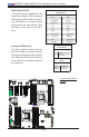
PWR LED Connector
PinDenitions
Pin Setting Denition
Pin 1 Anode (+)
Pin2 Cathode (-)
Pin3 NA
A
B