
User`s manual

2-28
X9DRD-7JLN4F/X9DRD-7LN4F Motherboard User’s Manual
JPME1
JI2C1
VGA1
I-SATA1
I-SATA0
I-SATA5
I-SATA4
I-SATA3
I-SATA2
JIPMB1
JPME2
JPL1
JBR1
JWD1
JPG1
JPB1
JVRM_I2C1
JVRM_I2C2
JVR1
FAN5
FAN6
FAN8
FAN7
FAN1
FAN2
FAN3
FAN4
JF2
T-SGPIO1
T-SGPIO2
JUSB6
JSD1
JBT1
JBAT1
JTPM1
JF1
JPI2C1
JOH1
JI2C2
JL1
JSTBY1
JUIDB
J4
JD1
LED3
LEDM1
LED2
LAN2/4
LAN1/3
CPU1
CPU2
CPU2
CPU1
CPU2
CPU1
PWR I2C
UID
P2-DIMME1
P2-DIMMF2
P2-DIMMF1
P2-DIMMG2
P2-DIMMG1
P2-DIMMH2
P2-DIMMH1
P1-DIMMA2
P1-DIMMA1
P1-DIMMB2
P1-DIMMB1
P1-DIMMC1
P1-DIMMC2
P1-DIMMD1
P1-DIMMD2
USB4/5USB8/9
SLOT1 PCI-E 3.0 X8
SLOT2 PCI-E 3.0 X8
SLOT3 PCI-E 3.0 X8
SLOT4 PCI-E 3.0 X8
SLOT5 PCI-E 3.0 X8
USB6
TPM/PORT80
BUZZER
CMOS CLEAR
SLOT6 PCI-E 3.0 X8
COM2
USB2/3
COM1
USB0/1
SP1
CPU2
IPMI_LAN
CPU2
CPU2
Battery
BIOS
JPW1
JPW2
24-Pin Main PWR
8-Pin PWR
JPW4
P2-DIMME2
JPW3
8-Pin PWR
4-Pin PWR
L-SAS4~7
L-SAS0~3
LSI SAS CTRL
Intel
PCH
JPS1
LAN
CTRL
BMC
CPU1
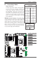
X9DRD-7LN4F
Rev. 1.02
KB/Mouse
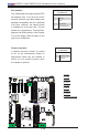
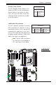
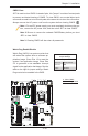
Chassis Intrusion
A Chassis Intrusion header is located
at JL1 on the motherboard. Attach an
appropriate cable from the chassis to
inform you of a chassis intrusion when
the chassis is opened.
Chassis Intrusion
PinDenitions
Pin# Denition
1 Intrusion Input
2 Ground
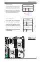
C
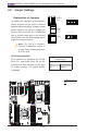
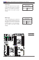
A. Fan 1
B. Fan 2
C. Fan 3
D. Fan 4
E. Fan 5
F. Fan 6
G. Fan 7
H. Fan 8
I. Chassis Intrusion
D
E
F
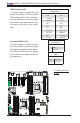
Fan Headers
This motherboard has eight system/CPU
fan headers (Fan 1~Fan 8) on the moth-
erboard. All these 4-pin fans headers are
backward compatible with the traditional
3-pin fans. However, fan speed control
is available for 4-pin fans only. The fan
speeds are controlled by Thermal Man-
agement via IPMI interface. (See Chapter
5 for more details.) See the table on the
right for pin denitions.
Fan Header
PinDenitions
Pin# Denition
1 Ground
2 +12V
3 Tachometer
4 PWR Modulation
G
A
B
I
H