
User`s manual

1-6
X9DRD-7LN4F-JBOD/X9DRD-7LN4F Motherboard User’s Manual
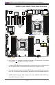
Warning!
To prevent damage to the power supply or the motherboard, please use a power supply
that contains a 24-pin, a 4-pin, and two 8-pin power connectors. Be sure to connect
the power supply to the 24-pin power connector (JPW1), and the two 8-pin power
connectors (JPW2/3) on the motherboard. Failure in doing so will void the manufacturer
warranty on your power supply and motherboard.
Note: X9DRD-7LN4F supports SAS Firmware IR mode, and X9DRD-
7LN4F-JBOD uses SAS Firmware IT Mode.
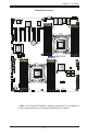
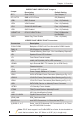
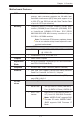
SP1 Onboard Buzzer (Internal Speaker)
(CPU1)Slots1/2/6,
(CPU2)Slot3/4/5
PCI-Express 3.0 x8 Slots (See Note Below)
(T-)SGPIO 1/2 Serial ATA (SATA) General Purpose I/O Header
(BP) USB 0/1, 2/3 Back Panel USB 0/1, 2/3
(FP) USB 4/5, USB 8/9 Front Panel Accessible USB Connections (4/5, 8/9)
(FP) USB 6 Type A USB Embedded Drive Connector
VGA Backpanel VGA Port
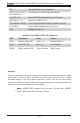
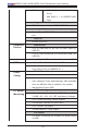
X9DRD-7LN4F-JBOD/-7LN4F LED Indicators
LED Description State Status
LED2 Standby PWR LED Green: On Standby PWR On
LED3 Rear UID LED Blue: On Unit Identied
LEDM1 BMC Heartbeat LED Green: Blinking BMC Normal