X9DRD-7LN4F-JBOD X9DRD-7LN4F USER’S MANUAL Revision 1.
The information in this User’s Manual has been carefully reviewed and is believed to be accurate. The vendor assumes no responsibility for any inaccuracies that may be contained in this document, and makes no commitment to update or to keep current the information in this manual, or to notify any person or organization of the updates. Please Note: For the most up-to-date version of this manual, please see our website at www.supermicro.com. Super Micro Computer, Inc.
Preface Preface This manual is written for system integrators, PC technicians and knowledgeable PC users. It provides information for the installation and use of the X9DRD-7LN4F-JBOD/X9DRD-7LN4F motherboard. About This Motherboard The Super X9DRD-7LN4F-JBOD/X9DRD-7LN4F motherboard supports dual Intel E5-2600 (Socket R) Series Processors that offer QPI (Intel QuickPath Interface) Technology (V.1.1), providing point-to-point connection with a transfer speed of up to 8.0 TG/s.
X9DRD-7LN4F-JBOD/X9DRD-7LN4F Motherboard User’s Manual Conventions Used in the Manual Pay special attention to the following symbols for proper system installation and to prevent damage to the system or injury to yourself: Warning: Important information given to ensure proper system installation or to prevent damage to the components or injury to yourself; Note: Additional information given to differentiate among various models or provides information for correct system setup.
Preface Contacting Supermicro Headquarters Address: Super Micro Computer, Inc. 980 Rock Ave. San Jose, CA 95131 U.S.A. Tel: +1 (408) 503-8000 Fax: +1 (408) 503-8008 Email: marketing@supermicro.com (General Information) support@supermicro.com (Technical Support) Web Site: www.supermicro.com Europe Address: Super Micro Computer B.V. Het Sterrenbeeld 28, 5215 ML 's-Hertogenbosch, The Netherlands Tel: +31 (0) 73-6400390 Fax: +31 (0) 73-6416525 Email: sales@supermicro.
X9DRD-7LN4F-JBOD/X9DRD-7LN4F Motherboard User’s Manual Table of Contents Preface Chapter 1 Overview 1-1 Overview.......................................................................................................... 1-1 1-2 Processor and Chipset Overview...................................................................1-11 1-3 Special Features............................................................................................ 1-12 1-4 PC Health Monitoring.................................
Table of Contents Front Control Panel........................................................................................ 2-19 Front Control Panel Pin Definitions............................................................... 2-20 NMI Button................................................................................................ 2-20 Power LED ............................................................................................... 2-20 HDD LED...............................................
X9DRD-7LN4F-JBOD/X9DRD-7LN4F Motherboard User’s Manual Serial ATA Ports........................................................................................ 2-38 SAS2 Ports ............................................................................................... 2-38 Chapter 3 Troubleshooting 3-1 Troubleshooting Procedures............................................................................ 3-1 Before Power On.................................................................................
Chapter 1: Overview Chapter 1 Overview 1-1 Overview Checklist Congratulations on purchasing your computer motherboard from an acknowledged leader in the industry. Supermicro boards are designed with the utmost attention to detail to provide you with the highest standards in quality and performance. Please check that the following items have all been included with your motherboard. If anything listed here is damaged or missing, contact your retailer. The following items are included in the retail box.
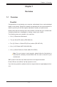
X9DRD-7LN4F-JBOD/X9DRD-7LN4F Motherboard User’s Manual Motherboard Image Note: All graphics shown in this manual were based upon the latest PCB Revision available at the time of publishing of the manual. The motherboard you've received may or may not look exactly the same as the graphics shown in this manual.
Chapter 1: Overview Motherboard Layout JPME2 Intel PCH JPME1 JBR1 JVRM_I2C2 JWD1 JVRM_I2C1 Rev. 1.02 USB6 8-Pin PWR P1-DIMMA1 P1-DIMMA2 P1-DIMMB1 P1-DIMMB2 JPW3 PWR I2C JPS1 JPI2C1 I-SATA1 I-SATA2 I-SATA3 I-SATA4 I-SATA5 T-SGPIO2 JSTBY1 8-Pin PWR JPW2 24-Pin Main PWR JD1 JF2 JOH1 USB8/9 USB4/5 T-SGPIO1 JPW1 FAN2 FAN1 L-SAS0~3 L-SAS4~7 JSD1 I-SATA0 LSI SAS CTRL 4-Pin PWR P2-DIMMG1 P2-DIMMG2 P2-DIMMH1 P2-DIMMH2 JPL1 TPM/PORT80 CPU1 SLOT1 PCI-E 3.0 X8 CPU1 SLOT2 PCI-E 3.
X9DRD-7LN4F-JBOD/X9DRD-7LN4F Motherboard User’s Manual X9DRD-7LN4F-JBOD/-7LN4F Quick Reference VGA1 LEDM1 LED3 JUIDB COM2 LAN2/4 USB2/3 LAN1/3 COM1 4-Pin PWR JPW4 LAN CTRL BMC USB0/1 UID KB/Mouse JPG1 JPB1 P2-DIMMG1 P2-DIMMG2 P2-DIMMH1 P2-DIMMH2 P2-DIMMF2 P2-DIMMF1 P2-DIMME2 P2-DIMME1 J4 JPL1 CPU1SLOT6 PCI-E 3.0 X8 JIPMB1 CPU2 SLOT5 PCI-E 3.0 X8 CPU2 SLOT4 PCI-E 3.0 X8 CPU2 SLOT3 PCI-E 3.0 X8 TPM/PORT80 JTPM1 CPU1 SLOT2 PCI-E 3.0 X8 JI2C1JI2C2 CPU1 SLOT1 PCI-E 3.
Chapter 1: Overview X9DRD-7LN4F-JBOD/-7LN4F Jumpers Jumper Description Default Setting JBT1 Clear CMOS See Chapter 3 JI2C1/JI2C2 SMB to PCI-E Slots Off (Disabled) JPB1 BMC Enabled Pins 1-2 (Enabled) JPG1 VGA Enabled Pins 1-2 (Enabled) JPL1 GLAN1/GLAN2 Enable Pins 1-2 (Enabled) JPS1 SAS Enabled Pins 1-2 (Enabled) JVRMI C1/2 CPU1/2 VRM I C Bus Pins 2-3 (Manufacture Default) JWD1 Watch Dog Timer Enable Pins 1-2 (Reset) 2 2 X9DRD-7LN4F-JBOD/-7LN4F Connectors Connectors Description
X9DRD-7LN4F-JBOD/X9DRD-7LN4F Motherboard User’s Manual SP1 Onboard Buzzer (Internal Speaker) (CPU1)Slots1/2/6, (CPU2)Slot3/4/5 PCI-Express 3.
Chapter 1: Overview Motherboard Features CPU • Dual Intel® E5-2600 Series (Socket R-LGA 2011) processors; each processor supports two full-width Intel QuickPath Interconnect (QPI) links (with support of up to 25.6 GT/s per QPI link and with Data Transfer Rate of up to 8.
X9DRD-7LN4F-JBOD/X9DRD-7LN4F Motherboard User’s Manual • RAID SATA RAID 0, 1, 5, 10 (Windows, Linux), SAS RAID 0, 1, 10 (X9DRD-7LN4F Only) Integrated IPMI 2.0 • IPMI 2.
Chapter 1: Overview System Management Dimensions • • Low noise fan speed control • • • • • UID (Unit Identification)/Remote UID PECI (Platform Environment Configuration Interface) 2.0 support System resource alert via SuperDoctor III SuperoDoctor III, Watch Dog, NMI Chassis Intrusion Header and Detection 13.00" (L) x 12.00" (W) (330.20 mm x 340.80 mm) Note: For IPMI Configuration Instructions, please refer to the Embedded IPMI Configuration User's Guide available @ http://www.supermicro.
X9DRD-7LN4F-JBOD/X9DRD-7LN4F Motherboard User’s Manual D P1 P0 CPU FRONT Socket 00 B PROCESSOR SANDYBRIDGE PE1 PE2 PE2 PE3 PE3 (AB) (AB) (CD) (AB) (CD) DMI #1 #2 PCIE 3.0 x8 SCU0 PCIE 3.0 x4 DDR3 HERMON WPCM450] VGA CONN PHY RTL8201F 2,3 TYPE-A 0,1 USB LPC SATA Gen3 6Gbps HDR 2X5 PCI 32 SATA SATA Gen3 6Gbps HDR 2X5 LAN2 RJ45 LAN4 RJ45 PCH C602J TPM HDR Port 80 LAN1 RJ45 LAN3 RJ45 SATA [0..1] PCIE 3.
Chapter 1: Overview 1-2 Processor and Chipset Overview Built upon the functionality and the capability of Intel E5-2600 Series (Socket R) processors and the C602J chipset, the X9DRD-7LN4F-JBOD/-7LN4F motherboard provides the performance and feature sets required for dual processor-based HPC/ Cluster/Database servers. With support of Intel QuickPath interconnect (QPI) Technology, the X9DRD-7LN4FJBOD/-7LN4F offers point-to-point serial interconnect interface with a transfer speed of up to 8.
X9DRD-7LN4F-JBOD/X9DRD-7LN4F Motherboard User’s Manual 1-3 Special Features Recovery from AC Power Loss The Basic I/O System (BIOS) provides a setting that determines how the system will respond when AC power is lost and then restored to the system. You can choose for the system to remain powered off (in which case you must press the power switch to turn it back on), or for it to automatically return to the power-on state. See the Advanced BIOS Setup section for this setting.
Chapter 1: Overview to provide you with warnings when the system temperature, CPU temperatures, voltages, and fan speeds go beyond a predefined range. 1-5 ACPI Features ACPI stands for Advanced Configuration and Power Interface. The ACPI specification defines a flexible and abstract hardware interface that provides a standard way to integrate power management features throughout a PC system, including its hardware, operating system and application software.
X9DRD-7LN4F-JBOD/X9DRD-7LN4F Motherboard User’s Manual It is strongly recommended that you use a high quality power supply that meets ATX power supply Specification 2.02 or above. It must also be SSI compliant. (For more information, please refer to the website at http://www.ssiforum.org/). Additionally, in areas where noisy power transmission is present, you may choose to install a line filter to shield the computer from noise.
Chapter 1: Overview Manageability Engine (ME) The Manageability Engine, which is an ARC controller embedded in the PCH, provides Server Platform Services (SPS) to your system. The services provided by SPS are different from those provided by the ME on client platforms.
X9DRD-7LN4F-JBOD/X9DRD-7LN4F Motherboard User’s Manual • Provides remote Hardware Health Monitoring via IPMI. Key features • Provides Network Management Security via remote access/console redirection. • • Supports the following Management tools: IPMIView, CLI (Command Line Interface) RMCP+ protocol supported Note 1: For more information on IPMI configuration, please refer to the IPMI User's Guide posted on our website at http://www.supermicro.com/ support/manuals/.
Chapter 2: Installation Chapter 2 Installation 2-1 Standardized Warning Statements The following statements are industry-standard warnings, provided to warn the user of situations which have the potential for bodily injury. Should you have questions or experience difficulty, contact Supermicro's Technical Support department for assistance. Only certified technicians should attempt to install or configure components.
X9DRD-7JLN4F/X9DRD-7LN4F Motherboard User’s Manual Attention Danger d'explosion si la pile n'est pas remplacée correctement. Ne la remplacer que par une pile de type semblable ou équivalent, recommandée par le fabricant. Jeter les piles usagées conformément aux instructions du fabricant. ¡Advertencia! Existe peligro de explosión si la batería se reemplaza de manera incorrecta. Reemplazar la batería exclusivamente con el mismo tipo o el equivalente recomendado por el fabricante.
Chapter 2: Installation Product Disposal Warning! Ultimate disposal of this product should be handled according to all national laws and regulations. 製品の廃棄 この製品を廃棄処分する場合、国の関係する全ての法律・条例に従い処理する必要が あります。 警告 本产品的废弃处理应根据所有国家的法律和规章进行。 警告 本產品的廢棄處理應根據所有國家的法律和規章進行。 Warnung Die Entsorgung dieses Produkts sollte gemäß allen Bestimmungen und Gesetzen des Landes erfolgen. ¡Advertencia! Al deshacerse por completo de este producto debe seguir todas las leyes y reglamentos nacionales.
X9DRD-7JLN4F/X9DRD-7LN4F Motherboard User’s Manual عند التخلص النهائي من هذا المنتج ينبغي التعامل معه وفقا لجميع القىانين واللىائح الىطنية Waarschuwing De uiteindelijke verwijdering van dit product dient te geschieden in overeenstemming met alle nationale wetten en reglementen. 2-2 Static-Sensitive Devices Electrostatic Discharge (ESD) can damage electronic components. To avoid damaging your system board, it is important to handle it very carefully.
Chapter 2: Installation 2-3 Processor and Heatsink Installation Warning: When handling the processor package, avoid placing direct pressure on the label area. Notes: Always connect the power cord last, and always remove it before adding, removing or changing any hardware components. Make sure that you install the processor into the CPU socket before you install the CPU heatsink. If you buy a CPU separately, make sure that you use an Intel-certified multi-directional heatsink only.
X9DRD-7JLN4F/X9DRD-7LN4F Motherboard User’s Manual 2. Press the second load lever labeled 'Close 1st' to release the load plate that covers the CPU socket from its locking position. 1 Press down on Load Lever 'Close 1st' WA R 2 Pull lever away from the socket WA R NI NG NI OP OP EN NG ! EN 1st ! 1st 3. With the lever labeled 'Close 1st' fully retracted, gently push down on the lever labelled 'Open 1st' to open the load plate. Lift the load plate to open it completely.
Chapter 2: Installation 1. Use your thumb, and index fingers to loosen the lever and open the load plate. 2. Using your thumb and index finger, hold the CPU on its edges. Align the CPU keys, which are semi-circle cutouts, against the socket keys. Socket Keys CPU Keys 3. Once they are aligned, carefully lower the CPU straight down into the socket. (Do not drop the CPU on the socket. Do not move the CPU horizontally or vertically.
X9DRD-7JLN4F/X9DRD-7LN4F Motherboard User’s Manual 4. With the CPU inside the socket, inspect the four corners of the CPU to make sure that the CPU is properly installed. 5. Close the load plate with the CPU inside the socket. Lock the lever labelled 'Close 1st' first, then lock the lever labelled 'Open 1st' second. Using your thumb gently push the load levers down to the lever locks. 1 2 Gently close the load plate. Push down and lock the lever labelled 'Close 1st'.
Chapter 2: Installation Installing a Passive CPU Heatsink 1. Do not apply any thermal grease to the heatsink or the CPU die -- the required amount has already been applied. 2. Place the heatsink on top of the CPU so that the four mounting holes are aligned with those on the Motherboard's and the Heatsink Bracket underneath. 3. Screw in two diagonal screws (i.e., the #1 and the #2 screws) until just snug (-do not over-tighten the screws to avoid possible damage to the CPU.) 4.
X9DRD-7JLN4F/X9DRD-7LN4F Motherboard User’s Manual Removing the Heatsink Warning: We do not recommend that the CPU or the heatsink be removed. However, if you do need to uninstall the heatsink, please follow the instructions below to uninstall the heatsink to prevent damage done to the CPU or the CPU socket. 1. Unscrew the heatsink screws from the motherboard in the sequence as shown in the illustration below. 2. Gently wriggle the heatsink to loosen it from the CPU.
Chapter 2: Installation 2-4 Installing and Removing the Memory Modules Note: Check Supermicro's website for recommended memory modules. CAUTION Exercise extreme care when installing or removing DIMM modules to prevent any possible damage. Installing & Removing DIMMs 1. Insert the desired number of DIMMs into the memory slots, starting with DIMM# A1. 2. Push the release tabs outwards on both ends of the DIMM slot to unlock it.
X9DRD-7JLN4F/X9DRD-7LN4F Motherboard User’s Manual Memory Support for the X9DRD-7LN4F-JBOD/7LN4F/ Motherboard The X9DRD-7LN4F-JBOD/-7LN4F motherboard supports 240-pin Registered (RDIMM)/Load Reduced (LRDIMM) ECC or Unbuffered (UDIMM) ECC/Non-ECC DDR3 800/1066/1333/1600 MHz memory modules of up to 512 GB in 16 DIMM modules. Please refer to our website a at http://www.supermicro.com/products/ motherboard.
Chapter 2: Installation Populating UDIMM (ECC/Non-ECC) Memory Modules Intel E5-2600 Series Processor UDIMM Memory Support Ranks Per DIMM & Data Width Memory Capacity Per DIMM Speed (MT/s) and Voltage Validated by Slot per Channel (SPC) and DIMM Per Channel (DPC) (See the Note below) 1 Slot Per Channel 2 Slots Per Channel 1DPC 1DPC 2DPC 1.35V 1.5V 1.35V 1.5V 1.35V 1.
X9DRD-7JLN4F/X9DRD-7LN4F Motherboard User’s Manual Populating LRDIMM (ECC) Memory Modules Intel E5-2600 Series Processor LRDIMM Memory Support Ranks Per DIMM & Data Width Memory Capacity Per DIMM Speed (MT/s) and Voltage Validated by Slot per Channel (SPC) and DIMM Per Channel (DPC) 1 Slot Per Channel (See the Note Below) 1DPC 2 Slots Per Channel 1DPC and 2DPC 1.35V 1.5V 1.35V 1.
Chapter 2: Installation 2-5 Motherboard Installation All motherboards have standard mounting holes to fit different types of chassis. Make sure that the locations of all the mounting holes for both motherboard and chassis match. Although a chassis may have both plastic and metal mounting fasteners, metal ones are highly recommended because they ground the motherboard to the chassis. Make sure that the metal standoffs click in or are screwed in tightly.
X9DRD-7JLN4F/X9DRD-7LN4F Motherboard User’s Manual Installing the Motherboard 1. Install the I/O shield into the chassis. 2. Locate the mounting holes on the motherboard. 3. Locate the matching mounting holes on the chassis. Align the mounting holes on the motherboard against the mounting holes on the chassis. 4. Install standoffs in the chassis as needed. 5. Install the motherboard into the chassis carefully to avoid damaging motherboard components. 6.
Chapter 2: Installation 2-6 Control Panel Connectors and I/O Ports The I/O ports are color coded in conformance with the PC 99 specification. See the picture below for the colors and locations of the various I/O ports. Back Panel Connectors and I/O Ports VGA1 LEDM1 LED3 JUIDB COM2 LAN2/4 USB2/3 LAN1/3 COM1 4 4-Pin PWR BMC USB0/1 UID JPW4 LAN CTRL KB/Mouse P2-DIMMG1 P2-DIMMG2 P2-DIMMH1 P2-DIMMH2 JPG1 JPB1 P2-DIMMF2 P2-DIMMF1 P2-DIMME2 P2-DIMME1 J4 JPL1 CPU1SLOT6 PCI-E 3.
X9DRD-7JLN4F/X9DRD-7LN4F Motherboard User’s Manual Serial Ports COM1 Two COM connections (COM1 & COM2) are located on the motherboard. COM1 is located on the Backplane I/O panel. COM2, located close to CPU1 Slot1, provides front access support. See the table on the right for pin definitions.
Chapter 2: Installation Universal Serial Bus (USB) FP USB (4/5, 8/9, USB 6) Pin Definitions Backplane USB (0/1, 2/3) Pin Definitions Four Universal Serial Bus ports (USB 0/1, USB 2/3) are located on the I/O USB 4, 8, 6, Pin # Definition Pin# Definition back panel. In addition, three USB headers, located close to the IO Hub, provides four front-accessible USB connections (USB 4/5, USB 8/9). One Type A connector (USB6) also supports front panel USB connection. (Cables are not included).
X9DRD-7JLN4F/X9DRD-7LN4F Motherboard User’s Manual Ethernet Ports LAN Ports Pin Definition Four Gigabit Ethernet ports (LAN1/2, LAN3/4) are located on the I/O back- Pin# Definition plane on the motherboard. In addition, an IPMI_Dedicated LAN is located above USB 0/1 ports on the backplane to provide KVM support for IPMI 2.0. All these ports accept RJ45 type cables. Please refer to the LED Indicator Section for LAN LED information.
Chapter 2: Installation Unit Identifier Switch/UID LED Indicators UID Switch A Unit Identifier (UID) Switch and two LED Indicators are located on the motherboard. The UID Switch is located next to the VGA port on the backplane. The Rear UID LED (LED3) is located next to the UID Switch. The Front Panel UID LED is located at Pins 7/8 of the Front Control Panel at JF1. Connect a cable to Pin 8 on JF1 for Front Panel UID LED indication.
X9DRD-7JLN4F/X9DRD-7LN4F Motherboard User’s Manual Front Control Panel JF1 contains header pins for various buttons and indicators that are normally located on a control panel at the front of the chassis. These connectors are designed specifically for use with Supermicro's server chassis. See the figure below for the descriptions of the various control panel buttons and LED indicators. Refer to the following section for descriptions and pin definitions.
Chapter 2: Installation Front Control Panel Pin Definitions NMI Button NMI Button Pin Definitions (JF1) The non-maskable interrupt button header is located on pins 19 and 20 of JF1. Refer to the table on the right for pin definitions. Power LED Pin# Definition 19 Control 20 Ground Power LED Pin Definitions (JF1) The Power LED connection is located on pins 15 and 16 of JF1. Refer to the table on the right for pin definitions. Pin# Definition 15 3.3V 16 PWR LED A. NMI B.
X9DRD-7JLN4F/X9DRD-7LN4F Motherboard User’s Manual HDD LED HDD LED Pin Definitions (JF1) The HDD LED connection is located on pins 13 and 14 of JF1. Attach a cable here to indicate HDD activity. See the table on the right for pin definitions. Pin# Definition 13 3.
Chapter 2: Installation Overheat (OH)/Fan Fail/PWR Fail/ UID LED OH/Fan Fail/ PWR Fail/Blue_UID LED Pin Definitions (JF1) Connect an LED cable to pins 7 and Pin# 8 of Front Control Panel to use the Overheat/Fan Fail/Power Fail and UID LED connections. The Red LED on pin 7 provides warnings of overheat, fan failure or power failure. The Blue LED on pin 8 works as the front panel UID LED indicator. The Red LED takes precedence over the Blue LED by default.
X9DRD-7JLN4F/X9DRD-7LN4F Motherboard User’s Manual Reset Button Reset Button Pin Definitions (JF1) The Reset Button connection is located on pins 3 and 4 of JF1. Attach it to a hardware reset switch on the computer case. Refer to the table on the right for pin definitions. Power Button The Power Button connection is located on pins 1 and 2 of JF1. Momentarily contacting both pins will power on/off the system.
Chapter 2: Installation 2-7 Connecting Cables ATX Power 24-pin Connector Pin Definitions Power Connectors Pin# Definition Pin # A 24-pin main power supply connector(JPW1), two 8-pin CPU power connectors (JPW2/3) and a 4-pin power connector (JPW4) are located on the motherboard. These power connectors meet the SSI EPS 12V specification and must be connected to your power supply to provide adequate power to the system. See the table on the right for pin definitions.
X9DRD-7JLN4F/X9DRD-7LN4F Motherboard User’s Manual Fan Headers Fan Header Pin Definitions This motherboard has eight system/CPU fan headers (Fan 1~Fan 8) on the motherboard. All these 4-pin fans headers are backward compatible with the traditional 3-pin fans. However, fan speed control is available for 4-pin fans only. The fan speeds are controlled by Thermal Management via IPMI interface. (See Chapter 5 for more details.) See the table on the right for pin definitions.
Chapter 2: Installation Internal Speaker Internal Buzzer (SP1) Pin Definition The Internal Speaker, located at SP1, can be used to provide audible indica- Pin# tions for various beep codes. See the table on the right for pin definitions. Refer to the layout below for the locations of the Internal Buzzer (SP1). Pos. (+) Beep In Pin 2 Neg.
X9DRD-7JLN4F/X9DRD-7LN4F Motherboard User’s Manual TPM Header/Port 80 TPM/Port 80 Header Pin Definitions A Trusted Platform Module/Port 80 header is located at JTPM1 to provide TPM support and Port 80 connection. Use this header to enhance system performance and data security. See the table on the right for pin definitions. Pin # Definition 2 GND 3 LFRAME# 4 <(KEY)> 5 LRESET# 6 +5V (X) 7 LAD 3 8 LAD 2 9 +3.
Chapter 2: Installation Power SMB (I2C) Connector PWR SMB Pin Definitions Power System Management Bus (I C) Connector (JPI2C1) monitors power 2 supply, fan and system temperatures. See the table on the right for pin definitions. Pin# Definition 1 Clock 2 Data 3 PWR Fail 4 Ground 5 +3.3V IPMB IPMB Header Pin Definitions A System Management Bus header for IPMI 2.0 is located at JIPMB1. Connect the appropriate cable here to use the IPMB I2C connection on your system.
X9DRD-7JLN4F/X9DRD-7LN4F Motherboard User’s Manual T-SGPIO 1/2 Headers T-SGPIO 1/2 Pin Definitions Two SGPIO (Serial Link General Purpose Input/Output) headers are located on the motherboard. T-SGPIO 1/2 provide onboard SATA support on the motherboard. See the table on the right for pin definitions.
Chapter 2: Installation Standby Power Header Standby PWR Pin Definitions The +5V Standby Power header is located at JSTBY1 on the motherboard. See the table on the right for pin definitions. (You must also have a card with a Standby Power connector and a cable to use this feature.
X9DRD-7JLN4F/X9DRD-7LN4F Motherboard User’s Manual 2-8 Jumper Settings Explanation of Jumpers Connector Pins To modify the operation of the motherboard, jumpers can be used to choose between optional settings. Jumpers create shorts between two pins to change the function of the connector. Pin 1 is identified with a square solder pad on the printed circuit board. See the motherboard layout pages for jumper locations.
Chapter 2: Installation CMOS Clear JBT1 is used to clear CMOS. Instead of pins, this "jumper" consists of contact pads to prevent accidental clearing of CMOS. To clear CMOS, use a metal object such as a small screwdriver to touch both pads at the same time to short the connection. Always remove the AC power cord from the system before clearing CMOS. Note 1. For an ATX power supply, you must completely shut down the system, remove the AC power cord, and then short JBT1 to clear CMOS. Note 2.
X9DRD-7JLN4F/X9DRD-7LN4F Motherboard User’s Manual VGA Enable VGA Enable Jumper Settings Jumper JPG1 allows the user to enable the onboard VGA connector. The default Jumper Setting setting is 1-2 to enable the connection. See the table on the right for jumper settings. Enabled (Default) 2-3 Disabled BMC Enable BMC Enable Jumper Settings Jumper JPB1 allows you to enable the embedded WPCM 450 BMC (Baseboard Management) Controller to provide IPMI 2.0/KVM support on the motherboard.
Chapter 2: Installation I2C Bus to PCI-Exp. Slots I2C to PCI-E slots Jumper Settings Use Jumpers JI C1 and JI C2 to connect the System Management Bus (I2C) to 2 2 Jumper Setting PCI-Express slots in order to improve PCI slot performance. These two jumpers are to be set at the same time. The default setting is Closed to enable the connections. See the table on the right for jumper settings. Enabled (Default) Open Disabled A.
X9DRD-7JLN4F/X9DRD-7LN4F Motherboard User’s Manual 2-9 Onboard LED Indicators Link LED Activity LED GLAN LEDs The Gigabit LAN ports are located on the IO Backplane on the motherboard. Each Ethernet LAN port has two LEDs. The Yellow LED indicates activity. The Link LED may be green, amber or off to indicate the speed of the connection. See the tables at right for more information.
Chapter 2: Installation Onboard Power LED Onboard PWR LED Indicator LED States An Onboard Power LED is located at LED2 on the motherboard. When this LED is on, the system is on. Be sure to turn off the system and unplug the power cord before removing or installing components. See the tables at right for more information.
X9DRD-7JLN4F/X9DRD-7LN4F Motherboard User’s Manual Unit Identification Switch/LED UID LED Status A Unit Identifier switch (UID) and a rear UID LED indicator (LED3) are located next to LAN ports on the back of the chassis. When the user pushes the rear UID switch, the rear UID LED (LED3) will be turned on. Push the UID switch again to turn off the LED indicator. The UID switch provides easy identification of a system unit that may be in need of service. See the tables on the right for more information.
Chapter 2: Installation 2-10 SATA/SAS Connections Serial ATA Ports SATA/SAS Pin Definitions There are six Serial ATA Ports (I-SATA1~I-SATA6) located on the motherboard, including four SATA2 ports and two SATA3 ports. These ports provide serial-link signal connections, which are faster than the connections of Parallel ATA. See the table on the right for pin definitions. SAS2 Ports Eight Serial_Attached_SCSI Ports (SAS0~3, 4~7) located on the motherboard to provide serial link connections.
X9DRD-7JLN4F/X9DRD-7LN4F Motherboard User’s Manual Notes 2-42
Chapter 3: Troubleshooting Chapter 3 Troubleshooting 3-1 Troubleshooting Procedures Use the following procedures to troubleshoot your system. If you have followed all of the procedures below and still need assistance, refer to the ‘Technical Support Procedures’ and/or ‘Returning Merchandise for Service’ section(s) in this chapter. Note: Always disconnect the power cord before adding, changing or installing any hardware components. Before Power On 1.
X9DRD-7LN4F-JBOD/X9DRD-7LN4F Motherboard User’s Manual No Video 1. If the power is on, but you have no video, remove all the add-on cards and cables. 2. Use the speaker to determine if any beep codes exist. Refer to Appendix A for details on beep codes. System Boot Failure If the system does not display POST or does not respond after the power is turned on, check the following: 1. Check for any error beep from the motherboard speaker.
Chapter 3: Troubleshooting Memory Errors When a No-Memory Beep Code is issued by the system, check the following: 1. Make sure that the memory modules are compatible with the system and that the DIMM modules are properly and fully installed. (For memory compatibility, refer to the Memory Compatibility Chart posted on our website @ http://www. supermicro.com.) 2. Check if different speeds of DIMMs have been installed. It is strongly recommended that you use the same RAM speed for all DIMMs in the system. 3.
X9DRD-7LN4F-JBOD/X9DRD-7LN4F Motherboard User’s Manual tings in the BIOS to make sure that the CPU and System temperatures are within the normal range. Also check the front panel Overheat LED, and make sure that the Overheat LED is not on. 5. Adequate power supply: Make sure that the power supply provides adequate power to the system. Make sure that all power connectors are connected. Please refer to our website for more information on minimum power requirement. 6.
Chapter 3: Troubleshooting 3-2 Technical Support Procedures Before contacting Technical Support, please take the following steps. Also, please note that as a motherboard manufacturer, Supermicro also sells motherboards through its channels, so it is best to first check with your distributor or reseller for troubleshooting services. They should know of any possible problem(s) with the specific system configuration that was sold to you. 1.
X9DRD-7LN4F-JBOD/X9DRD-7LN4F Motherboard User’s Manual • 3-3 Distributors: For immediate assistance, please have your account number ready when placing a call to our technical support department. We can be reached by e-mail at support@supermicro.com. Battery Removal and Installation Battery Removal To remove the onboard battery, follow the steps below: 1. Power off your system and unplug your power cable. 2. Locate the onboard battery as shown below. Battery Lock Battery Battery Holder 3.
Chapter 3: Troubleshooting 3. Insert the battery into the battery holder and push it down until you hear a click to ensure that the battery is securely locked. Warning: When replacing a battery, be sure to only replace it with the same type. 3-4 Frequently Asked Questions Question: What are the various types of memory that my motherboard can support? Answer: The motherboard supports Registered (RDIMM)/Load Reduced (LRDIMM) ECC or Unbuffered (UDIMM) ECC/Non-ECC DDR3 modules.
X9DRD-7LN4F-JBOD/X9DRD-7LN4F Motherboard User’s Manual not discard a used battery in the garbage or a public landfill. Please comply with the regulations set up by your local hazardous waste management agency to dispose of your used battery properly. (Refer to Section 3-3 on Page 3-6.) 3-5 Returning Merchandise for Service A receipt or copy of your invoice marked with the date of purchase is required before any warranty service will be rendered.
Chapter 4: AMI BIOS Chapter 4 BIOS 4-1 Introduction This chapter describes the AMI BIOS Setup utility for the X9DRD-7LN4F-JBOD/ X9DRD-7LN4F It also provides the instructions on how to navigate the AMI BIOS Setup utility screens. The AMI ROM BIOS is stored in a Flash EEPROM and can be easily updated. Starting BIOS Setup Utility To enter the AMI BIOS Setup utility screens, press the key while the system is booting up. Note: In most cases, the key is used to invoke the AMI BIOS setup screen.
X9DRD-7LN4F-JBOD/X9DRD-7LN4F Motherboard User’s Manual How To Change the Configuration Data The configuration data that determines the system parameters may be changed by entering the AMI BIOS Setup utility. This Setup utility can be accessed by pressing at the appropriate time during system boot. Note: For AMI UEFI BIOS Recovery, please refer to the UEFI BIOS Recovery User Guide posted @http://www.supermicro.com/support/manuals/.
Chapter 4: AMI BIOS System Date/System Time Use this option to change the system time and date. Highlight System Time or System Date using the arrow keys. Enter new values through the keyboard and press . Press the key to move between fields. The date must be entered in Day MM/DD/YY format. The time is entered in HH:MM:SS format. (Note: The time is in the 24-hour format. For example, 5:30 P.M. appears as 17:30:00.).
X9DRD-7LN4F-JBOD/X9DRD-7LN4F Motherboard User’s Manual 4-3 Advanced Setup Configurations Select the Advanced tab to access the following submenu items. Boot Feature Quiet Boot This feature allows the user to select bootup screen display between POST messages and the OEM logo. Select Disabled to display the POST messages. Select Enabled to display the OEM logo instead of the normal POST messages. The options are Enabled and Disabled.
Chapter 4: AMI BIOS at bootup and allow the drives that are attached to these host adaptors to function as bootable disks. If this item is set to Disabled, the ROM BIOS of the host adaptors will not capture Interrupt 19, and the drives attached to these adaptors will not function as bootable devices. The options are Enabled and Disabled.
X9DRD-7LN4F-JBOD/X9DRD-7LN4F Motherboard User’s Manual • Processor Cores • Intel HT (Hyper-Threading) Technology • Intel VT-x Technology • Intel SMX Technology • L1 Data Cache / L1 Code Cache • L2 Cache • L3 Cache CPU Speed This item displays the speed of the CPU installed in Socket 1/Socket 2. 64-bit This item indicates if the CPU installed in Socket 1 or Socket 2 supports 64-bit technology.
Chapter 4: AMI BIOS Execute-Disable Bit (Available if supported by the OS & the CPU) Select Enabled to enable the Execute Disable Bit which will allow the processor to designate areas in the system memory where an application code can execute and where it cannot, thus preventing a worm or a virus from flooding illegal codes to overwhelm the processor or damage the system during an attack. The default is Enabled. (Refer to Intel and Microsoft Web sites for more information.
X9DRD-7LN4F-JBOD/X9DRD-7LN4F Motherboard User’s Manual CPU Power Management Configuration This submenu allows the user to configure the following CPU Power Management settings. Power Technology Select Energy Efficiency to support power-saving mode. Select Custom to customize system power settings. Select Disabled to disable power-saving settings. The options are Disabled, Energy Efficient, and Custom.
Chapter 4: AMI BIOS Package C-State limit (Available when Power Technology is set to Custom) This feature allows the user to set the limit on the C-State package register. The options are C0, C2, C6, and No Limit. Energy/Performance Bias Use this feature to select an appropriate fan setting to achieve maximum system performance (with maximum cooling) or maximum energy efficiency with maximum power saving). The fan speeds are controlled by the firmware management via IPMI 2.0.
X9DRD-7LN4F-JBOD/X9DRD-7LN4F Motherboard User’s Manual Chipset Configuration North Bridge This feature allows the user to configure the settings for the Intel North Bridge. Integrated IO Configuration Intel® VT-d Select Enabled to enable Intel Virtualization Technology support for Direct I/O VT-d by reporting the I/O device assignments to the VMM (Virtual Machine Monitor) through the DMAR ACPI Tables.
Chapter 4: AMI BIOS IIO 2 PCIe Port Bifurcation Control This submenu configures the following IO PCIe Port Bifurcation Control settings for IIO 2 PCIe ports to determine how the available PCI-Express lanes to be distributed between the PCI-Exp. Root ports. QPI Configuration Current QPI Link This item displays the current status of the QPI Link. Current QPI Frequency This item displays the frequency of the QPI Link.
X9DRD-7LN4F-JBOD/X9DRD-7LN4F Motherboard User’s Manual DIMM Information CPU Socket 1 DIMM Information, CPU Socket 2 DIMM Information The status of the memory modules detected by the BIOS will be displayed as detected by the BIOS. Memory Mode When Independent is selected, all DIMMs are available to the operating system. When Mirroring is selected, the motherboard maintains two identical copies of all data in memory for data backup.
Chapter 4: AMI BIOS correctable error, the error is corrected and sent to the requestor (the original source). Memory is updated as well. Select Enabled to use Demand Scrubbing for ECC memory correction. The options are Enabled and Disabled. Data Scrambling Select Enabled to enable data scrambling to ensure data security and integrity. The options are Disabled and Enabled. Device Tagging Select Enabled to support device tagging. The options are Disabled and Enabled.
X9DRD-7LN4F-JBOD/X9DRD-7LN4F Motherboard User’s Manual Port 60/64 Emulation Select Enabled to enable I/O port 60h/64h emulation support for the legacy USB keyboard so that it can be fully supported by the operating systems that does not recognize a USB device. The options are Disabled and Enabled. EHCI Hand-Off This item is for operating systems that do not support Enhanced Host Controller Interface (EHCI) hand-off. When enabled, EHCI ownership change will be claimed by the EHCI driver.
Chapter 4: AMI BIOS Port 0~5 Hot Plug Select Enabled to enable hot-plug support for a particular port, which will allow the user to change a hardware component or device without shutting down the system. The options are Enabled and Disabled. Staggered Spin Up Select Enabled to enable Staggered Spin-up support to prevent excessive power consumption caused by multiple HDDs spinning-up simultaneously. The options are Enabled and Disabled.
X9DRD-7LN4F-JBOD/X9DRD-7LN4F Motherboard User’s Manual SERR# Generation Select Enabled to allow a PCI device to generate an SERR number for a PCI Bus Signal Error Event. The options are Enabled and Disabled. Maximum Payload Select Auto to allow the system BIOS to automatically set the maximum payload value for a PCI-E device to enhance system performance. The options are Auto, 128 Bytes and 256 Bytes.
Chapter 4: AMI BIOS VGA Priority This feature allows the user to select the graphics adapter to be used as the primary boot device. The options are Onboard, and Offboard. Network Stack Select Enabled enable PXE (Preboot Execution Environment) or UEFI (Unified Extensible Firmware Interface) for network stack support. The options are Enabled and Disabled. Super IO Configuration Super IO Chip: This item displays the Super IO chip used in the motherboard.
X9DRD-7LN4F-JBOD/X9DRD-7LN4F Motherboard User’s Manual Change Settings This option specifies the base I/O port address and the Interrupt Request address of Serial Port 2. Select Disabled to prevent the serial port from accessing any system resources. When this option is set to Disabled, the serial port becomes unavailable.
Chapter 4: AMI BIOS client computer. A lower transmission speed may be required for long and busy lines. The options are 9600, 19200, 38400, 57600 and 115200 (bits per second). Data Bits Use this feature to set the data transmission size for Console Redirection. The options are 7 Bits and 8 Bits. Parity A parity bit can be sent along with regular data bits to detect data transmission errors. Select Even if the parity bit is set to 0, and the number of 1's in data bits is even.
X9DRD-7LN4F-JBOD/X9DRD-7LN4F Motherboard User’s Manual Putty KeyPad This feature selects Function Keys and KeyPad settings for Putty, which is a terminal emulator designed for the Windows OS. The options are VT100, LINUX, XTERMR6, SC0, ESCN, and VT400. Serial Port for Out-of-Band Management/Windows Emergency Management Services (EMS) The submenu allows the user to configure Console Redirection settings to support Out-of-Band Serial Port management.
Chapter 4: AMI BIOS Data Bits, Parity, Stop Bits The status of these features is displayed. ACPI Settings Use this feature to configure Advanced Configuration and Power Interface (ACPI) power management settings for your system. ACPI Sleep State Use this feature to select the ACPI State when the system is in sleep mode. Select S1 (CPU_Stop_Clock) to erase all CPU caches and stop executing instructions. Power to the CPU(s) and RAM is maintained, but RAM is refreshed.
X9DRD-7LN4F-JBOD/X9DRD-7LN4F Motherboard User’s Manual Pending Operation Use this item to schedule an operation for the security device. The options are None, Enable Take Ownership, Disable Take Ownership, and TPM Clear. Note: During restart, the computer will reboot in order to execute the pending operation and change the state of the security device. Current Status Information: This item displays the information regarding the current TPM status.
Chapter 4: AMI BIOS TPM Support: Trusted Platform support TPM State: Trusted Platform state ME Subsystem This feature displays the following ME Subsystem Configuration settings. • ME BIOS Interface Version • ME Version iSCSI Configuration: This item displays iSCSI configuration information: iSCSI Initiator Name This item displays the name of the iSCSI Initiator, which is a unique name used in the world. The name must use IQN format.
X9DRD-7LN4F-JBOD/X9DRD-7LN4F Motherboard User’s Manual Blink LEDs This feature allows the user to specify the duration for LEDs to blink. The range is from 0 ~ 15 seconds. The default setting is 0.
Chapter 4: AMI BIOS 4-4 Event Logs Select the Event Logs tab to access the following submenu items. Change SMBIOS Event Log Settings This feature allows the user to configure SMBIOS Event settings. Enabling/Disabling Options SMBIOS Event Log Select Enabled to enable SMBIOS (System Management BIOS) Event Logging during system boot. The options are Enabled and Disabled. Runtime Error Logging Support Select Enabled to support Runtime Error Logging. The options are Enabled and Disabled.
X9DRD-7LN4F-JBOD/X9DRD-7LN4F Motherboard User’s Manual Erasing Settings Erase Event Log Select Enabled to erase the SMBIOS (System Management BIOS) Event Log, which is completed before a event logging is initialized upon system reboot. The options are No, Yes, Next reset, and Yes, Every reset. When Log is Full Select Erase Immediately to immediately erase SMBIOS error event logs that exceed the limit when the SMBIOS event log is full.
Chapter 4: AMI BIOS 4-5 IPMI Select the IPMI (Intelligent Platform Management Interface) tab to access the following submenu items. IPMI Firmware Revision This item indicates the IPMI firmware revision used in your system. IPMI Status This item indicates the status of the IPMI firmware installed in your system. System Event Log Enabling/Disabling Options SEL Components Select Enabled for all system event logging at bootup. The options are Enabled and Disabled.
X9DRD-7LN4F-JBOD/X9DRD-7LN4F Motherboard User’s Manual When SEL is Full This feature allows the user to decide what the BIOS should do when the system event log is full. Select Erase Immediately to erase all events in the log when the system event log is full. The options are Do Nothing and Erase Immediately. Custom EFI Logging Options Log EFI Status Codes Select Enabled to log EFI (Extensible Firmware Interface) Status Codes, Error Codes or Progress Codes. The options are Enabled and Disabled.
Chapter 4: AMI BIOS Gateway IP Address This item displays the Gateway IP address for this computer. This should be in decimal and in dotted quad form (i.e., 192.168.10.253). 4-6 Boot This submenu allows the user to configure the following boot settings for the system. Boot Option Priorities Boot Option #1, Boot Option #2, Boot Option #3, etc. Use this feature to specify the sequence of boot device priority.
X9DRD-7LN4F-JBOD/X9DRD-7LN4F Motherboard User’s Manual 4-7 Security This menu allows the user to configure the following security settings for the system. Password Check Use this feature to determine when a password entry is required. Select Setup to require the password only when entering setup. Select Always to require the password when entering setup and on each boot. The options are Setup and Always.
Chapter 4: AMI BIOS 4-8 Save & Exit This submenu allows the user to configure the Save and Exit settings for the system. Discard Changes and Exit Select this option to quit the BIOS Setup without making any permanent changes to the system configuration, and reboot the computer. Select Discard Changes and Exit, and press .
X9DRD-7LN4F-JBOD/X9DRD-7LN4F Motherboard User’s Manual Discard Changes Select this feature and press to discard all the changes and return to the BIOS setup. When the dialog box appears, asking you if you want to load previous values, select Yes to load the values previous saved, or select No to keep the changes you've made so far. Restore Optimized Defaults Select this feature and press to load the optimized default settings that help optimize system performance.
Appendix A: BIOS POST Error Codes Appendix A BIOS Error Beep Codes During the POST (Power-On Self-Test) routines, which are performed at each system boot, errors may occur. Non-fatal errors are those which, in most cases, allow the system to continue to boot. The error messages normally appear on the screen. Fatal errors will not allow the system to continue with bootup procedure. If a fatal error occurs, you should consult with your system manufacturer for possible repairs.
X9DRD-7LN4F-JBOD/X9DRD-7LN4F Motherboard User’s Manual Notes A-2
Appendix B: Software Installation Instructions Appendix B Software Installation Instructions B-1 Installing Software Programs The Supermicro ftp site contains drivers and utilities for your system at ftp://ftp. supermicro.com. Some of these must be installed, such as the chipset driver. After accessing the ftp site, go into the CDR_Images directory and locate the ISO file for your motherboard. Download this file to create a CD/DVD of the drivers and utilities it contains.
X9DRD-7LN4F-JBOD/X9DRD-7LN4F Motherboard User’s Manual Note 2. When making a storage driver diskette by booting into a Driver CD, please set the SATA Configuration to "Compatible Mode" and configure SATA as IDE in the BIOS Setup. After making the driver diskette, be sure to change the SATA settings back to your original settings. B-2 Configuring SuperDoctor III The SuperDoctor® III program is a web-based management tool that supports remote management capability.
Appendix B: Software Installation Instructions SuperDoctor III Interface Display Screen-II (Remote Control) Note: SD III Software Revision 1.0 can be downloaded from our Web Site at: ftp://ftp.supermicro.com/utility/Supero_Doctor_III/. You can also download the SDIII User's Guide at: . For Linux, we will recommend using Supero Doctor II.
X9DRD-7LN4F-JBOD/X9DRD-7LN4F Motherboard User’s Manual Notes B-4
(Disclaimer Continued) The products sold by Supermicro are not intended for and will not be used in life support systems, medical equipment, nuclear facilities or systems, aircraft, aircraft devices, aircraft/emergency communication devices or other critical systems whose failure to perform be reasonably expected to result in significant injury or loss of life or catastrophic property damage.