
User`s manual
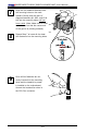
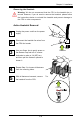

Chapter 2: Installation
2-11
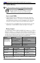
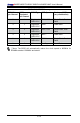
Table 2 - DDR3 ECC Registered (RDIMM) Memory Support
RDIMM 1Gb (x8 DRAM) 2Gb (x8 DRAM)
Single Rank Up to 6GB
(6 x 1GB DIMM Modules)
Up to 12GB
(6 x 2GB DIMM Modules)
Dual Rank Up to 12GB
(6 x 2GB DIMM Modules)
Up to 24GB
(6 x 4GB DIMM Modules)
Quad Rank Up to 16GB
(4 x 4GB DIMM Modules)**
Up to 32GB
(4 x 8GB DIMM Modules)**
Note: All other memory sizes, types, die, density, that are not listed in these tables
are NOT supported. **For Quad Rank RDIMMs, only Slot 1 and Slot 2 (DIMM A
and DIMM B) are populated per channel.
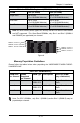
Memory Population Guidelines
Please follow the tables below when populating the X8SIE/X8SIE-F/X8SI6-F/X8SIE-
LN4/X8SIE-LN4F.
DDR3 ECC UDIMM Memory
DIMM Slots
per Channel
DIMMs
Populated
per Channel
DIMM Type POR Speeds Ranks per DIMM
(any combination)
3 1 Unbuffered
DDR3 ECC
1066, 1333 Single Rank, Dual
Rank
3 2 Unbuffered
DDR3 ECC
1066, 1333 Single Rank, Dual
Rank
3 3 N/A Not Supported Single Rank, Dual
Rank
DIMM A, Channel 1
DIMM B, Channel 1
DIMM A, Channel 2
DIMM B, Channel 2
R1312
4
1
JPW2
1
JPW1
5 1
+
B1
JBT1
+
J8
J5
Y2
JS8
JS7
J13
J14
JWOL
JWF1
JF1
JSPK
J25
FAN2
FAN1
1
FAN5
FAN3
FAN4
T-SGPIO2
JI2C1
JIBTN
JL1
JPUSB1
1
JLED
JPL4
JPL3 JPL1JPL2
JPG1
JPS1
R572
J28
D1
J12
LE3
LE2
LE6
LE8
LE7
LE4
SPKR1
U89
U2
USB4
USB5
FAIL
PWR
NIC_LED4
NIC_LED3
2-3:DISABLE
1-2:ENABLE
JPL4:LAN4
1-2:ENABLE
2-3:DISABLE
JPL3:LAN3
LED
UID
2-3:Disable
1-2:Enable
JPB:
JPT1:
1-2:Enable
2-3:Disable
DOM PWR
JWOL:
I-SATA5 I-SATA4
UID
DIMM2A
DIMM2B
DIMM2C
DIMM1B
DIMM1A
SW1
SAS4~7
SAS0~3
Chassis Intrusion
Wake on Lan
CMOS CLEAR
USB2/3
1-2:ENABLE
2-3:DISABLE
JPL2:LAN2
JPL1:LAN1
2-3:DISABLE
1-2:ENABLE
JPB:BMC
JPI2C:PWR I2C
JSPK:Buzzer/Speaker
COM2
FLOPPY
DDR3 1066/1333 UDIMM/RDIMM required
VGA
COM1
JL1:
JPS1:SAS
LAN2/LAN4
LAN1/LAN3
JPUSB1:B/P USB WAKE UP
1-2:ENABLE
2-3:DISABLE
JI2C1/JI2C2
USB10/11
SLOT6 PCI-E 2.0 X16
2-3:Disable
1-2:Enable
JAR:
PSU ALARM RST
CPU
JLED1:Power LED
OFF:Disable
ON:Enable
2-3:Disable
1-2:Enable
REV:1.00
X8SIE
DESIGNED IN USA
2-3:DISABLE
1-2:ENABLE
JF1
ON
LED LED
PWRHDD
NIC1
NIC2
OH/FF
RST
PWR
I-SATA3
I-SATA2
I-SATA0
SLOT2 PCI-E X4 on X8
SLOT1 PCI 33MHZ
KB/MOUSE
DIMM1C
JPG1: VGA
C A
LE5
JI2C2
JPB
DIMM C, Channel 1
DIMM C, Channel 2
Note: For ECC UDIMMs , only Slot 1 (DIMM A) and/or Slot 2 (DIMM B) may be
populated per channel.
Figure A