
User`s manual


Chapter 2: Installation
2-37
T-SGPIO0
T-SGPIO1
JF1
JWOL
JWD
JPUSB1
JPAC
JPL2
JPL1
JLED
JPI1
JPUSB2
SPKR1
B1
Fan4
Fan3
LE1
JWOR
JL1
JI2C2
JI2C1
JOH
JPW1
COM2
COM1
JPW2
SMBUS_PS1
JD1
1
JPW3
I-SATA5
I-SATA4
I-SATA3
I-SATA2
I-SATA1
I-SATA0
DIMM3A
DIMM3B
JBT1
USB 10/11
HD Audio (7.1)
S/PDIF
LAN2/USB6~7
USB 0~3
1394_1
USB9
USB8
Audio FP
LAN1/USB4~5
Slot6 PCI-E x16 Gen2
Slot5 PCI-E x4 in x8 Gen2
Slot4 PCI-E x16 Gen2
Slot2 PCI-X 133/100 MHz
CD-In
KB/Mouse
Floppy
X8SAX
DIMM2B
DIMM2A
DIMM1B
DIMM1A
LAN CTRL
LAN CTRL
S I/O
1394_2
Slot3 PCI 33MHz
Slot1 PCI-X 133/100 MHz
Fan2
Audio CTRL
CPU
Intel
North Bridge
Intel ICH10R
South Bridge
Battery
Intel PXH-V
1394a
CTRL
BIOS
X58
Fan1 - CPU
Fan5
Fan6
A
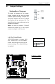
A. Floppy
Floppy Connector
The oppy connector is located near
the PCI-X Slot 1 on the motherboard.
See the table on the right for pin
denitions.
Floppy Drive Connector
PinDenitions
Pin# Denition Pin # Denition
1 Ground 2 FDHDIN
3 Ground 4 Reserved
5 Key 6 FDEDIN
7 Ground 8 Index
9 Ground 10 Motor Enable
11 Ground 12 Drive Select B
13 Ground 14 Drive Select B
15 Ground 16 Motor Enable
17 Ground 18 DIR
19 Ground 20 STEP
21 Ground 22 Write Data
23 Ground 24 Write Gate
25 Ground 26 Track 00
27 Ground 28 Write Protect
29 Ground 30 Read Data
31 Ground 32 Side 1 Select
33 Ground 34 Diskette
Note the following when con-
necting the oppy cable:
• The oppy disk drive cable has
seven twisted wires.
• A red mark on a wire typically
designates the location of pin 1.
• A single oppy disk drive ribbon
cable has 34 wires and two con-
nectors to provide for two oppy
disk drives. The connector with
twisted wires always connects to
drive A, and the connector that
does not have twisted wires always
connects to drive B.