
User`s manual


Chapter 2: Installation
2-31
T-SGPIO0
T-SGPIO1
JF1
JWOL
JWD
JPUSB1
JPAC
JPL2
JPL1
JLED
JPI1
JPUSB2
SPKR1
B1
Fan4
Fan3
LE1
JWOR
JL1
JI2C2
JI2C1
JOH
JPW1
COM2
COM1
JPW2
SMBUS_PS1
JD1
1
JPW3
I-SATA5
I-SATA4
I-SATA3
I-SATA2
I-SATA1
I-SATA0
DIMM3A
DIMM3B
JBT1
USB 10/11
HD Audio (7.1)
S/PDIF
LAN2/USB6~7
USB 0~3
1394_1
USB9
USB8
Audio FP
LAN1/USB4~5
Slot6 PCI-E x16 Gen2
Slot5 PCI-E x4 in x8 Gen2
Slot4 PCI-E x16 Gen2
Slot2 PCI-X 133/100 MHz
CD-In
KB/Mouse
Floppy
X8SAX
DIMM2B
DIMM2A
DIMM1B
DIMM1A
LAN CTRL
LAN CTRL
S I/O
1394_2
Slot3 PCI 33MHz
Slot1 PCI-X 133/100 MHz
Fan2
Audio CTRL
CPU
Intel
North Bridge
Intel ICH10R
South Bridge
Battery
Intel PXH-V
1394a
CTRL
BIOS
X58
Fan1 - CPU
Fan5
Fan6
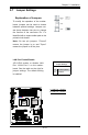
2-7 Jumper Settings
Explanation of Jumpers
To modify the operation of the mother-
board, jumpers can be used to choose
between optional settings. Jumpers cre-
ate shorts between two pins to change
the function of the connector. Pin 1 is
identied with a square solder pad on the
printed circuit board.
Note: On two pin jumpers, "Closed"
means the jumper is on and "Open"
means the jumper is off the pins.
A
A. LAN Port 1 Enable
B. LAN Port 2 Enable
LAN Port Enable/Disable
JPL1/JPL2 enable or disable LAN
Port 1/LAN Port 2 on the mother-
board. See the table on the right for
jumper settings. The default setting
is enabled.
GLAN Enable
Jumper Settings
Pin# Denition
1-2 Enabled (default)
2-3 Disabled
B