
User`s manual


Chapter 2: Installation
2-29
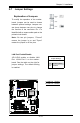
1394a_1/1394a_2 Connections
1394a_1 and 1394a_2 provide the
IEEE 1394 connections on the moth-
erboard. See the tables on the right for
pin denitions.
1394a_1
PinDenitions
Pin# Den. Pin# Den
1 PTPA0+ 2 PTPA0-
3 GND 4 GND
5 PTPB0+ 6 PTPB0-
7 PWR 1394 8 PWR 1394
10 ZX
J1394a_2
PinDenitions
Pin# Den. Pin# Den
1 PTPA1+ 2 PTPA1-
3 GND 4 GND
5 PTPB1+ 6 PTPB1-
7 PWR 1394 8 PWR 1394
10 ZY
T-SGPIO
PinDenitions
Pin# Denition Pin Denition
1 NC 2 NC
3 Ground 4 DATA Out
5 Load 6 Ground
7 Clock 8 NC
T-SGPIO 0/1 Headers
Two T-SGPIO (Serial-Link General
Purpose Input/Output) headers are
located next to the front USB ports
10/11 on the motherboard. These
headers are used to communicate
with the enclosure management chip
in the system. See the table on the
right for pin denitions. Refer to the
board layout below for the locations
of the headers.
NC: No Connections
T-SGPIO0
T-SGPIO1
JF1
JWOL
JWD
JPUSB1
JPAC
JPL2
JPL1
JLED
JPI1
JPUSB2
SPKR1
B1
Fan4
Fan3
LE1
JWOR
JL1
JI2C2
JI2C1
JOH
JPW1
COM2
COM1
JPW2
SMBUS_PS1
JD1
1
JPW3
I-SATA5
I-SATA4
I-SATA3
I-SATA2
I-SATA1
I-SATA0
DIMM3A
DIMM3B
JBT1
USB 10/11
HD Audio (7.1)
S/PDIF
LAN2/USB6~7
USB 0~3
1394_1
USB9
USB8
Audio FP
LAN1/USB4~5
Slot6 PCI-E x16 Gen2
Slot5 PCI-E x4 in x8 Gen2
Slot4 PCI-E x16 Gen2
Slot2 PCI-X 133/100 MHz
CD-In
KB/Mouse
Floppy
X8SAX
DIMM2B
DIMM2A
DIMM1B
DIMM1A
LAN CTRL
LAN CTRL
S I/O
1394_2
Slot3 PCI 33MHz
Slot1 PCI-X 133/100 MHz
Fan2
Audio CTRL
CPU
Intel
North Bridge
Intel ICH10R
South Bridge
Battery
Intel PXH-V
1394a
CTRL
BIOS
X58
Fan1 - CPU
Fan5
Fan6
A. 1394a_1
B. 1394a_2
C. T-SPGIO0
D. T-SPGIO1
A
B
C
D