
User`s manual


Chapter 3: Installation
3-29
P1-DIMM7A
FAN
5
P2-DIMM3A
BMC CTRL
LAN CTRL
Intel 82576
Winbond
JPRST1
Intel
IOH 7500
LSI 2108
SAS CTRL
Intel ICH 10R
Battery
BIOS
J59
BBU
LED5
LED6
LED7
LED8
LED9
P5V_STBY
OHLED
JOH1
BT2
SP1
JP10
JBT1
JP1
JLPC1
JP4
JP5
JP6
X8QBE-F
Rev. 1.11
FAN 11
U70
JPWR3
I-SATA1
I-SATA3
I-SATA2
LED26
JPWR1JPWR2
JPWR5
JPWR4
JPI2C1
JWD1
JPL1
JPB1
JPS1
JPG1
JPT1
JL1
1
J35
J40
JUID_OW1
U101
JUIDB1
D10
Slot2 PCI-E 2.0 X16/X8
(UPPER)
(LOWER)
VGA
COM1
JD1
JWOR
BMCRST
JP3
LAN2
I-SATA5
I-SATA4
I-SATA0
PORT80
USB2/3
USB5
Slot3 PCI-E 2.0 X8
Slot1 PCI-E 2.0 X8
Slot4 PCI-E 2.0 X16/X8
JF1
IPMB
COM2
FAN2
FAN1
FAN3
FAN4
FAN6
FAN7
FAN10
FAN8
FAN9
LAN1
USB0/1
IPMI_LAN
SAS4~7
SAS0~3
P3-DIMM1A
P3-DIMM8A
P3-DIMM7A
P3-DIMM6A
P3-DIMM5A
P3-DIMM4A
P3-DIMM3A
P3-DIMM2A
P4-DIMM5A
P4-DIMM6A
P4-DIMM7A
P4-DIMM8A
P4-DIMM1A
P4-DIMM2A
P4-DIMM3A
P4-DIMM4A
P2-DIMM6A
P2-DIMM5A
P2-DIMM8A
P2-DIMM7A
P2-DIMM1A
P2-DIMM2A
P2-DIMM4A
P1-DIMM8A
P1-DIMM6A
P1-DIMM5A
P1-DIMM4A
P1-DIMM3A
P1-DIMM2A
P1-DIMM1A
CPU1
CPU2
CPU3
UID_SWITCH
CPU4
UID_LED
BMC_HB
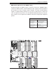
3-7 Jumper Settings
Explanation of Jumpers
To modify the operation of the mother-
board, jumpers can be used to choose
between optional settings. Jumpers cre-
ate shorts between two pins to change
the function of the connector. Pin 1
is identifi ed with a square solder pad
on the printed circuit board. See the
motherboard layout pages for jumper
locations.
Note: On two pin jumpers,
"Closed" means the jumper
is on and "Open" means the
jumper is off the pins.
Connector
Pins
Jumper
Cap
Setting
Pin 1-2 short
3 2 1
3 2 1
GLAN Enable/Disable
JPL1 enables or disables the GLAN
Port1/GLAN Port2 on the mother-
board. See the table on the right for
jumper settings. The default setting is
Enabled.
GLAN Enable
Jumper Settings
Jumper Setting Defi nition
1-2 Enabled (default)
2-3 Disabled
A
A. GLAN Ports Enable