X8QB6-F X8QBE-F USER’S MANUAL Revision 1.
The information in this User’s Manual has been carefully reviewed and is believed to be accurate. The vendor assumes no responsibility for any inaccuracies that may be contained in this document, and makes no commitment to update or to keep current the information in this manual, or to notify any person or organization of the updates. Please Note: For the most up-to-date version of this manual, please see our Website at www.supermicro.com. Super Micro Computer, Inc.
Preface Preface This manual is written for system integrators, PC technicians and knowledgeable PC users. It provides information for the installation and use of the X8QB6-F/X8QBE-F motherboard. About This Motherboard The X8QB6-F/X8QBE-F motherboard supports the Intel 7500 Series Socket-LS processor, the first generation chip multiprocessor (CMP) platform that offers Intel QuickPath Interconnect (QPI) Technology, providing point-to-point system interface, replacing the Front Side Bus.
X8QB6-F/X8QBE-F Motherboard User’s Manual Conventions Used in the Manual Special attention should be given to the following symbols for proper installation and to prevent damage to the system or injury to yourself: Danger/Caution: Instructions to be strictly followed to prevent catastrophic system failure or to avoid bodily injury Warning: Important information given to ensure proper system installation or to prevent damage to the components Note: Additional information given to differentiate between vario
Preface Contacting Supermicro Headquarters Address: Super Micro Computer, Inc. 980 Rock Ave. San Jose, CA 95131 U.S.A. Tel: +1 (408) 503-8000 Fax: +1 (408) 503-8008 Email: marketing@supermicro.com (General Information) support@supermicro.com (Technical Support) Website: www.supermicro.com Europe Address: Super Micro Computer B.V. Het Sterrenbeeld 28, 5215 ML 's-Hertogenbosch, The Netherlands Tel: +31 (0) 73-6400390 Fax: +31 (0) 73-6416525 Email: sales@supermicro.
X8QB6-F/X8QBE-F Motherboard User’s Manual Table of Contents Preface Chapter 1 Quick Installation Guide 1-1 Installing the CPU ........................................................................................... 1-1 1-2 Installing the CPU/Heatsink/ CPU Fans ......................................................... 1-1 1-3 Installing the Memory Modules ....................................................................... 1-2 1-4 Installing the I/O Shield ......................................
Table of Contents 3-5 Control Panel Connectors/I/O Ports...............................................................3-11 Back Panel Connectors/I/O Ports ..................................................................3-11 Back Panel I/O Port Locations and Definitions ............................................3-11 Serial Ports ............................................................................................... 3-12 Video Connection ..........................................................
X8QB6-F/X8QBE-F Motherboard User’s Manual SAS2 Enable (X8QB6-F only) .................................................................. 3-32 BMC Enable ............................................................................................ 3-32 BMC Reset .............................................................................................. 3-33 3-8 Onboard LED Indicators ............................................................................... 3-34 GLAN LEDs .............................
Chapter 1: Quick Installation Guide Chapter 1 Quick Installation Guide 1-1 Installing the CPU 2 A CPU Key B 1 A. Press the socket clip down to unlock it. Gently lift the socket clip to open the load plate. B. Align the CPU key with the socket key. D C CPU Pin 1 C. Align CPU Pin 1 against Socket Pin 1. Once they are aligned, lower the CPU down to the socket. D. Once the CPU is fully seated on the socket, press the socket clip down to lock it.
X8QB6-F/X8QBE-F Motherboard User’s Manual 1-3 Installing the Memory Modules A B C A. Press the release tabs on the both B. Use two thumbs to press both ends of the DIMM socket outwards to notches of the module straight down unlock it. into the DIMM socket. Align the key on the DIMM module against that of the DIMM socket. C. Press the release tabs on the ends of the DIMM module inwards to lock it.
Chapter 1: Quick Installation Guide 1-5 Installing the Motherboard A B X8QBE-F Rev.1.11 C 1-6 D Connecting the Power Supply X8QBE-F Rev.1.11 B A Note: Please connect the 24-pin power connector and three of the four 8-pin power connectors to the power supply to provide adequate power supply to your system.
X8QB6-F/X8QBE-F Motherboard User’s Manual 1-7 A 1-8 Installing Internal Peripherals B SATA/SAS2 Drives Add-on Cards Installing External Peripherals IPMI LAN Serial Port VGA Port (COM1) USB 0/1 LAN 1/2 Ports UID Switch 1-4
Chapter 2: Overview Chapter 2 Overview 2-1 Overview Checklist Congratulations on purchasing your computer motherboard from an acknowledged leader in the industry. Supermicro boards are designed with the utmost attention to detail to provide you with the highest standards in quality and performance. Please check that the following items have all been included with your motherboard. If anything listed here is damaged or missing, contact your retailer. The following items are included in the retail box.
X8QB6-F/X8QBE-F Motherboard User’s Manual Motherboard Image Note: All graphics shown in this manual were based upon the latest PCB Revision available at the time of publishing of the manual. The motherboard you've received may or may not look exactly the same as the graphics shown in this manual.
Chapter 2: Overview Motherboard Layout Intel 82576 BMCRST Winbond BMC CTRL LAN CTRL COM1 VGA FAN8 FAN9 SP1 IPMI_LAN P3-DIMM8A P3-DIMM7A P3-DIMM5A P3-DIMM6A P3-DIMM1A P3-DIMM3A P3-DIMM2A P3-DIMM4A P1-DIMM8A P1-DIMM7A P1-DIMM6A P1-DIMM5A P1-DIMM2A P1-DIMM1A P1-DIMM4A P1-DIMM3A Slot4 PCI-E 2.0 X16/X8 Slot3 PCI-E 2.0 X8 JPG1 JPT1 JUID_OW1 JLPC1PORT80 JWD1JP10 J35 JBT1 USB0/1 LAN1 (LOWER) LAN2 (UPPER) JPS1 Slot1 PCI-E 2.0 X8 JPB1 JD1 Slot2 PCI-E 2.
X8QB6-F/X8QBE-F Motherboard User’s Manual X8QB6-F/X8QBE-F Quick Reference Intel 82576 BMCRST Winbond BMC CTRL LAN CTRL COM1 VGA FAN8 FAN9 SP1 IPMI_LAN P3-DIMM8A P3-DIMM7A P3-DIMM5A P3-DIMM6A P3-DIMM1A P3-DIMM3A P3-DIMM2A P3-DIMM4A P1-DIMM8A P1-DIMM7A P1-DIMM6A P1-DIMM5A P1-DIMM2A P1-DIMM1A P1-DIMM4A P1-DIMM3A Slot4 PCI-E 2.0 X16/X8 Slot3 PCI-E 2.0 X8 JPG1 JPT1 JUID_OW1 JLPC1PORT80 JWD1JP10 J35 JBT1 USB0/1 LAN1 (LOWER) LAN2 (UPPER) JPS1 Slot1 PCI-E 2.
Chapter 2: Overview X8QB6-F/X8QBE-F Jumpers Jumper Description Default Setting JBT1 Clear CMOS See Chapter 3 JPB1 BMC Enabled Pins 1-2 (Enabled) JPG1 VGA Enabled Pins 1-2 (Enabled) JPL1 GLAN1/GLAN2 Enable Pins 1-2 (Enabled) JPRST1 BMC Reset Off (Normal) JPS1 (X8QB6-F only) SAS2 Enabled Pins 1-2 (Enabled) JPT1 TPM Enabled Pins 1-2 (Enabled) JWD1 Watch Dog Pins 1-2 (Reset) X8QB6-F/X8QBE-F Connectors Connectors Description BT2 Onboard Battery (See Chpt.
X8QB6-F/X8QBE-F Motherboard User’s Manual T-SGPIO 1/2 Serial_Link General Purpose I/O Headers BP USB 0/1 Back Panel USB 0/1 USB 2/3, USB 5 Front Panel Accessible USB Connections UID Switch UID (Unit Identifier) Switch VGA Backpanel VGA Port X8QB6-F/X8QBE-F LED Indicators LED Description State Status D10 BMC Heartbeat LED Green: Blinking Normal LED 8 Standby PWR LED Green: On SB Power On LED 26 UID LED Blue: On (Windows OS), Unit Identified Blinking (Linux) Warning! • To prevent d
Chapter 2: Overview Motherboard Features CPU • Four Intel® 7500 Series (Socket LS-LGA 1567) processors; each processor supports four full-width Intel QuickPath Interconnect (QPI) links (with support of up to 25.6 GT/s per QPI link and with Data Transfer Rate of up to 6.4 GT/s per direction) Memory • Integrated memory controller supports: 1. 32 240-pin DDR3-1066 RDIMMs running at speeds of 1066/978/800 MHz (via an onboard buffer) 2.
X8QB6-F/X8QBE-F Motherboard User’s Manual SATA Connections I/O Devices • • SATA Ports Six (6) RAID (Win- RAID 0, 1, 5, 10 dows) • RAID (Linux) RAID 0, 1, 10 SAS2 Connections • • • LSI SAS2 2108 Controller SAS2 Ports 0~3, 4~7 RAID Support RAID 0, 1, 5, 6, 10, 50, 60 Integrated IPMI 2.0 • IPMI 2.
Chapter 2: Overview CPU Monitoring PC Health Monitoring • Onboard voltage monitors for CPU1 Vcore, CPU2 Vcore, CPU3 Vcore, CPU4 Vcore, NIC Vcore, BMC Vcore, AUX Vcore, Standby ME Vcore, 12V Scale, 1.5V, 3.3V Vcc(V), 3.3VSB, Battery Voltage, and IOPV12.
QPI 6.4GT/s PCIE-G2x8x2 PCIE-G2x8 Slot3 PCIE-G2x16 Slot5 PCIE-G2x8 Slot6 PCIE-G2x16 PCIE-G2x8x2 SAS x4 SAS x4 LSI 2018 SAS CTRL BIOS USB Ports x4 SPI USB 2.0 Mill Brook DDR3 800/1066 (x2) DDR3 800/1066 (x2) DDR3 800/1066 (x2) Mill Brook Mill Brook DDR3 800/1066 (x2) DDR3 800/1066 (x2) Mill Brook Mill Brook Kawela Dual GLAN GLAN GLAN RJ45 10/100LAN QPI#0 QPI#1 RMII PHY WPCM450R 10/100 PCI Intel 7500 Rear USB 1.0 Winbond BMC Video (w/Video, KVM, IOH#1 USB 2.
Chapter 2: Overview 2-2 Chipset Overview Built upon the functionality and the capability of the Intel 7500 platform, the X8QB6-F/X8QBE-F motherboard provides the performance and support for quad_processor-based HPC/Cluster/Database servers. The 7500 platform consists of the 7500 Series Socket-LS (LGA 1567) processor, the 7500 (IOH), and the ICH10R (South Bridge).
X8QB6-F/X8QBE-F Motherboard User’s Manual 2-3 Special Features Recovery from AC Power Loss The Basic I/O System (BIOS) provides a setting for you to determine how the system will respond when AC power is lost and then restored to the system. You can choose for the system to remain powered off (in which case you must press the power switch to turn it back on), or for it to automatically return to the power- on state. See the Advanced BIOS Setup section for this setting. The default setting is Last State.
Chapter 2: Overview System Resource Alert This feature is available when used with Supero Doctor III in the Windows OS environment or used with Supero Doctor II in Linux. Supero Doctor is used to notify the user of certain system events. For example, you can configure Supero Doctor to provide you with warnings when the system temperature, CPU temperatures, voltages and fan speeds go beyond a predefined range. 2-5 ACPI Features ACPI stands for Advanced Configuration and Power Interface.
X8QB6-F/X8QBE-F Motherboard User’s Manual connectors. Be sure to connect these power supply connectors to the 24-pin (JPWR3) and three of the four 8-pin power connectors (JPWR1, JPWR2, JPWR4, or JPWR5) on the motherboard. Failure to do so will void the manufacturer warranty on your power supply and motherboard. It is strongly recommended that you use a high quality power supply that meets ATX power supply Specification 2.02 or above. It must also be SSI compliant.
Chapter 3: Installation Chapter 3 Installation 3-1 Static-Sensitive Devices Electrostatic Discharge (ESD) can damage electronic components. To avoid damaging your system board, it is important to handle it very carefully. The following measures are generally sufficient to protect your equipment from ESD. Precautions • Use a grounded wrist strap designed to prevent static discharge. • Touch a grounded metal object before removing the board from the antistatic bag.
X8QB6-F/X8QBE-F Motherboard User's Manual 3-2 Processor and Heatsink Installation When handling the processor package, avoid placing direct pressure on ! the label area of the fan. Notes: 1. Always connect the power cord last, and always remove it before adding, removing or changing any hardware components. Make sure that you install the processor into the CPU socket before you install the CPU heatsink. 2.
Chapter 3: Installation 4. After removing the plastic cap, using your thumb and the index finger, hold the CPU at the north and south center edges. 5. Align the CPU key, which is a semi-circle cutout, against the socket key, which is the notch below the gold color dot on the side of the socket. CPU Key CPU Pin 1 6. Align Pin 1 on the CPU against Pin 1 on the CPU socket. 7. Once both CPU and the socket are aligned, carefully lower the CPU straight down into the socket.
X8QB6-F/X8QBE-F Motherboard User's Manual Installing a Passive CPU Heatsink 1. Apply the proper amount of thermal grease (with thickness of up to 0.13 mm) to the heatsink. 2. Place the heatsink on top of the CPU so that the two mounting holes on the heatsink are aligned with those on the retention mechanism. 3. Insert two push-pins on the sides of the heatsink through the mounting holes on the motherboard, and turn the push-pins clockwise to lock them.
Chapter 3: Installation Removing the Passive Heatsink Warning: We do not recommend that the CPU or the heatsink be removed. However, if you do need to remove the heatsink, please follow the instructions below to uninstall the heatsink to avoid damaging the CPU or other components. 1. Unplug the power cord from the power supply. 2. Press down the push-pin on the heatsink, and turn counter-clock-wise to loosen it. Repeat the same step to loosen the second push-pin. 3.
X8QB6-F/X8QBE-F Motherboard User's Manual 3-3 Installing and Removing the Memory Modules Note: Check Supermicro's website for recommended memory modules. CAUTION Exercise extreme care when installing or removing DIMM modules to prevent any possible damage. Installing & Removing DIMMs 1. Insert the desired number of DIMMs into the memory slots, starting with P1DIMM #1A. (For best performance, please use the memory modules of the same type and speed in the same bank.) 2.
Chapter 3: Installation Memory Support for the X8QB6-F/X8QBE-F Motherboard The X8QB6-F/X8QBE-F Motherboard supports up to 512 GB Registered ECC DDR3 1066 MHz memory in 32 DIMM slots. These RDIMMs run at 800/978/1066 via a memory buffer. For the latest memory updates, please refer to our website a at http://www.supermicro.com/products/motherboard. Processor & Memory Module Population Configuration For memory to work properly, follow the tables below for memory installation.
X8QB6-F/X8QBE-F Motherboard User's Manual 4 CPUs & 8 DIMMs CPU1/CPU2/CPU3/CPU4 P1-1A/P1-3A, P2-1A/P2-3A,P3-1A/P3-3A + P4-1A/P4-3A 4 CPUs & 10 DIMMs CPU1/CPU2/CPU3/CPU4 P1-1A/P1-3A/P1-5A/P1-7A, P2-1A/P2-3A,P3-1A/P3-3A + P4-1A/P4-3A 4 CPUs & 12 DIMMs CPU1/CPU2/CPU3/CPU4 P1-1A/P1-3A/P1-5A/P1-7A, P2-1A/P2-3A/P2-5A/P2-7A, P3-1A/P3-3A, P4-1A/P4-3A 4 CPUs & 14 DIMMs CPU1/CPU2/CPU3/CPU4 P1-1A/P1-3A/P1-5A/P1-7A, P2-1A/P2-3A/P2-5A/P2-7A,P3-1A/P3-3A/P3-5A/P3-7A, P4-1A/P4-3A 4 CPUs & 16 DIMMs CPU1/CPU2/CPU3/C
Chapter 3: Installation 3-4 Motherboard Installation All motherboards have standard mounting holes to fit different types of chassis. Make sure that the locations of all the mounting holes for both motherboard and chassis match. Although a chassis may have both plastic and metal mounting fasteners, metal ones are highly recommended because they ground the motherboard to the chassis. Make sure that the metal standoffs click in or are screwed in tightly.
X8QB6-F/X8QBE-F Motherboard User's Manual Installing the Motherboard 1. Install the I/O shield into the chassis. 2. Locate the mounting holes on the motherboard. 3. Locate the matching mounting holes on the chassis. Align the mounting holes on the motherboard against the mounting holes on the chassis. 4. Install standoffs in the chassis as needed. 5. Install the motherboard into the chassis carefully to avoid damaging motherboard components. 6.
Chapter 3: Installation 3-5 Control Panel Connectors/I/O Ports The I/O ports are color coded in conformance with the PC 99 specification. See the picture below for the colors and locations of the various I/O ports. Back Panel Connectors/I/O Ports Intel 82576 BMC CTRL LAN CTRL COM1 VGA FAN8 FAN9 IPMI_LAN P3-DIMM8A P3-DIMM7A P3-DIMM6A P3-DIMM5A P3-DIMM1A P3-DIMM2A P1-DIMM8A P3-DIMM3A P3-DIMM4A P1-DIMM6A P1-DIMM7A P1-DIMM5A P1-DIMM2A P1-DIMM1A P1-DIMM4A P1-DIMM3A Slot4 PCI-E 2.
X8QB6-F/X8QBE-F Motherboard User's Manual Serial Ports Serial COM) Ports Pin Definitions Two COM connections (COM1 & COM2) are located on the motherboard. Pin # COM1 is located on the Backplane I/O panel. COM2, located close to the 7500 IOH, provides front accessible serial support. See the table on the right for pin definitions.
Chapter 3: Installation Universal Serial Bus (USB) FP USB (2/3, 5) Pin Definitions Backplane USB (0/1) Pin Definitions Two Universal Serial Bus ports (USB 0/1) are located on the I/O back panel. Pin# Definition Additional Front Panel USB connec- 1 +5V tions (USB 2/3, USB5) are on the 2 PO- 3 PO+ 4 Ground motherboard to provide front chassis access. (Cables are not included).
X8QB6-F/X8QBE-F Motherboard User's Manual Ethernet Ports LAN Ports Pin Definition Two Ethernet ports (LAN1/LAN2) are located on the I/O backplane on the motherboard. In addition, an IPMI_ Dedicated LAN is located above USB 0/1 ports on the backplane to provide KVM support for IPMI 2.0. All these ports accept RJ45 type cables.
Chapter 3: Installation Unit Identifier Switch UID Switch A Unit Identifier (UID) Switch and two LED Indicators are located on the motherboard. Pin# Definition 1 Ground The UID Switch is located next to the LAN 2 Ground ports on the backplane. The Rear UID LED 3 Button In (LED26) is located next to the UID Switch. The Front Panel UID LED is located at Pins 4 Ground UID LED (LE2) Status 7/8 of the Front Control Panel at JF1.
X8QB6-F/X8QBE-F Motherboard User's Manual Front Control Panel JF1 contains header pins for various buttons and indicators that are normally located on a control panel at the front of the chassis. These connectors are designed specifically for use with Supermicro's server chassis. See the figure below for the descriptions of the various control panel buttons and LED indicators. Refer to the following section for descriptions and pin definitions.
Chapter 3: Installation Front Control Panel Pin Definitions NMI Button NMI Button Pin Definitions (JF1) The non-maskable interrupt button header is located on pins 19 and 20 of JF1. Refer to the table on the right for pin definitions. Pin# Definition 19 Control 20 Ground Power LED Power LED Pin Definitions (JF1) The Power LED connection is located on pins 15 and 16 of JF1. Refer to the table on the right for pin definitions. Pin# Definition 15 3.3V 16 PWR LED A. NMI B.
X8QB6-F/X8QBE-F Motherboard User's Manual HDD LED HDD LED Pin Definitions (JF1) The HDD LED connection is located on pins 13 and 14 of JF1. Attach a cable here to indicate HDD activity. See the table on the right for pin Pin# Definition 13 3.3V Standby 14 HD Active definitions.
Chapter 3: Installation Overheat (OH)/Fan Fail/PWR Fail/ OH/Fan Fail/PWR Fail/UID LED Pin Definitions (JF1) UID LED Pin# Connect an LED cable to OH/Fan Fail/ Front UID LED connection on pins 7 and 8 of JF1 to provide advanced Definition 7 Red+ (Blue LED Cathode) 8 Blue+ (OH/Fan Fail/PWR Fail/ UID LED) warnings of chassis overheat or fan failure. It also works as the front panel OH/Fan Fail Indicator Status UID LED indicator. The Red LED takes precedence over the Blue LED State by default.
X8QB6-F/X8QBE-F Motherboard User's Manual Reset Button Reset Button Pin Definitions (JF1) The Reset Button connection is located on pins 3 and 4 of JF1. Attach it to a hardware reset switch on the computer case. Refer to the table on the right for Pin# Definition 3 Reset 4 Ground pin definitions. Power Button Power Button Pin Definitions (JF1) The Power Button connection is located on pins 1 and 2 of JF1. Momentarily contacting both pins will power on/off the system.
Chapter 3: Installation 3-6 Connecting Cables ATX Power 24-pin Connector Pin Definitions Pin# Definition Pin # Definition Power Connectors 13 +3.3V 1 +3.3V A 24-pin main power supply connector(JPWR3) and four 8-pin CPU 14 -12V 2 +3.3V 15 COM 3 COM PWR connectors (JPWR1~2, JPWR4~5) 16 PS_ON 4 +5V are located on the motherboard. These pow- 17 COM 5 COM er connectors meet the SSI EPS 12V specification.
X8QB6-F/X8QBE-F Motherboard User's Manual Fan Headers Fan Header Pin Definitions This motherboard has ten system/CPU fan headers (Fan 1 to Fan10) on the motherboard. (Fan 11: reserved) All these 4-pin fans headers are backward compatible with the traditional 3-pin fans. However, fan speed control is available Pin# Definition 1 Ground 2 +12V 3 Tachometer 4 PWR Modulation for 4-pin fans only.
Chapter 3: Installation Internal Speaker Internal Buzzer (SP1) Pin Definition The Internal Speaker, located at SP1, can be used to provide audible indica- Pin# tions for various beep codes. See the table on the right for pin definitions. Definitions Pin 1 Pos. (+) Beep In Pin 2 Neg. (-) Alarm Speaker Refer to the layout below for the locations of the Internal Buzzer (SP1).
X8QB6-F/X8QBE-F Motherboard User's Manual TPM Header/Port 80 TPM/Port 80 Header Pin Definitions A Trusted Platform Module/Port 80 header is located at LPCI to provide Pin # TPM support and Port 80 connection. Use this header to enhance system performance and data security. See the table on the right for pin definitions. Definition Pin # Definition 1 LCLK 2 GND 3 LFRAME# 4 <(KEY)> 5 LRESET# 6 +5V (X) 7 LAD 3 8 LAD 2 9 +3.
Chapter 3: Installation Power SMB (I2C) Connector PWR SMB Pin Definitions Power System Management Bus (I2C) Connector (JPI 2C) monitors power supply, fan and system temperatures. See the table on the right for pin definitions. Pin# Definition 1 Clock 2 Data 3 PWR Fail 4 Ground 5 +3.3V IPMB IPMB Header Pin Definitions A System Management Bus header for IPMI 2.0 is located at IPMB. Connect the appropriate cable here to use the IPMB I2C connection on your system.
X8QB6-F/X8QBE-F Motherboard User's Manual T-SGPIO 1/2 Headers T-SGPIO Pin Definitions Two SGPIO (Serial-Link General Purpose Input/Output) headers are located on the motherboard. These headers support Serial_Link interface for onboard SATA connections. See the table on the right for pin defini- Pin# Definition Pin Definition 1 NC 2 NC 3 Ground 4 Data 5 Load 6 Ground 7 Clock 8 NC Note: NC= No Connection tions. Wake-On-Ring The Wake-On-Ring header is located at JWOR.
Chapter 3: Installation BBU Header (Optional for the X8QB6-F Only) A Battery-Backup Unit (BBU) header is located at J59 on the X8QB6-F. When enabled, the BBU provides extended battery backup support for onboard SAS to prevent data loss due to a battery 'power shortage.' To enable extended battery support, an optional battery backup accessory kit is required. Please contact our sales at Supermicro to purchase an LSI 2108 SAS Battery Backup Accessory kit.
X8QB6-F/X8QBE-F Motherboard User's Manual Unit Identification Switch/LED UID Switch (UID) Pin Definitions A Unit Identifier switch (UID) and a rear UID LED indicator (LED26) are located next to Pin# Definition Fan10 on the back of the chassis. When the user pushes the rear UID switch, the rear UID LED (LED26) will be turned on. Push the UID switch again to turn off the 1 Ground 2 Ground 3 Button In 4 Ground LED indicator.
Chapter 3: Installation 3-7 Jumper Settings Explanation of Jumpers Connector Pins 3 2 1 3 2 1 To modify the operation of the motherboard, jumpers can be used to choose between optional settings. Jumpers create shorts between two pins to change the function of the connector. Jumper Cap Pin 1 is identified with a square solder pad Setting on the printed circuit board. See the motherboard layout pages for jumper locations.
X8QB6-F/X8QBE-F Motherboard User's Manual CMOS Clear JBT1 is used to clear CMOS. Instead of pins, this "jumper" consists of contact pads to prevent accidental clearing of CMOS. To clear CMOS, use a metal object such as a small screwdriver to touch both pads at the same time to short the connection. Always remove the AC power cord from the system before clearing CMOS. Note 1. For an ATX power supply, you must completely shut down the system, remove the AC power cord, and then short JBT1 to clear CMOS.
Chapter 3: Installation VGA Enable VGA Enable Jumper Settings Jumper JPG1 allows the user to enable the onboard VGA connectors. The Jumper Setting default setting is 1-2 to enable the connection. See the table on the right for Definition 1-2 Enabled (Default) 2-3 Disabled jumper settings. TPM Support Enable TPM Support Enable Jumper Settings JPT1 allows the user to enable TPM (Trusted Platform Modules) support to enhance data integrity and system security.
X8QB6-F/X8QBE-F Motherboard User's Manual SAS2 Enable (X8QB6-F only) SAS2 Enable Jumper Settings Close pins 1-2 of JPS1 to enable SAS2 (Serial_Attached_SCSI) support on the Jumper Setting X8QB6-F motherboard. See the table on 1-2 Enabled (Default) the right for jumper settings. The default 2-3 Disabled Definition setting is enabled. BMC Enable BMC Enable Jumper Settings Jumper JPB1 allows you to enable the embedded WPCM 450 BMC (Baseboard Management) Controller to provide IPMI 2.
Chapter 3: Installation BMC Reset BMC Reset Jumper Settings Use Jumper JPRST1 to reset the BMC settings on the motherboard. See the Jumper Setting table on the right for jumper settings. A Intel 82576 BMC CTRL LAN CTRL Closed BMC Reset Closed Normal (Default) COM1 VGA A.
X8QB6-F/X8QBE-F Motherboard User's Manual 3-8 Onboard LED Indicators Activity Link LED LED GLAN LEDs There are two GLAN ports on the motherboard. Each Gigabit Ethernet LAN port Rear View (when facing the rear side of the chassis) has two LEDs. The Yellow (Left) LED in- GLAN Activity Indicator (Left) LED Status dicates activity. The Link LED on the right may be green, amber or off to indicate the speed of the connection.
Chapter 3: Installation Rear UID LED UID LED LED Status The rear UID LED is located at LED26 on the backplane. This LED is used in Color/State OS Status conjunction with the rear UID switch to provide easy identification of a system Blue: On Windows OS Unit Identified Blue: Blinking Linux OS Unit Identified that might be in need of service. Refer to UID Switch on Page 3-15 for more information.
X8QB6-F/X8QBE-F Motherboard User's Manual Onboard Power LED Onboard PWR LED Indicator LED Status An Onboard Power LED is located at LED 8 on the motherboard. When this LED is LED Color Definition Off System Off (PWR cable not connected) system and unplug the power cord before Green System On removing or installing components. See the tables at right for more information. Green: Flashing Quickly ACPI S1 State Green: Flashing Slowly ACPI S3 (STR) State on, the system is on.
Chapter 3: Installation 3-9 Serial ATA Connections Serial ATA Ports Serial ATA/SAS2 Pin Definitions There are six Serial ATA Ports (ISATA0~I-SATA 5) located on the Pin# Definition motherboard. These por ts, sup- 1 Ground ported by the Intel ICH10R South 2 TX_P Bridge, provide serial-link signal connections, which are faster than the 3 TX_N 4 Ground connections of Parallel ATA. See the 5 RX_N table on the right for pin definitions.
X8QB6-F/X8QBE-F Motherboard User's Manual Notes 3-38
Chapter 4: Troubleshooting Chapter 4 Troubleshooting 4-1 Troubleshooting Procedures Use the following procedures to troubleshoot your system. If you have followed all of the procedures below and still need assistance, refer to the ‘Technical Support Procedures’ and/or ‘Returning Merchandise for Service’ section(s) in this chapter. Note: Always disconnect the power cord before adding, changing or installing any hardware components. Before Power On 1.
X8QB6-F/X8QBE-F Motherboard User's Manual No Video 1. If the power is on, but you have no video, remove all the add-on cards and cables. 2. Use the speaker to determine if any beep codes exist. Refer to Appendix A for details on beep codes. System Boot Failure If the system does not display POST or does not respond after the power is turned on, check the following: 1. Check for any error beep from the motherboard speaker. • If there is no error beep, try to turn on the system without DIMM modules.
Chapter 4: Troubleshooting Memory Errors When a No_Memory_Beep_Code is issued by the system, check the following: 1. Make sure that the memory modules are compatible with the system and that the DIMM modules are properly and fully installed. (For memory compatibility, refer to the Memory Compatibility Chart posted on our Website @ http://www. supermicro.com.) 2. Check if different speeds of DIMMs have been installed. It is strongly recommended that you use the same RAM speed for all DIMMs in the system. 3.
X8QB6-F/X8QBE-F Motherboard User's Manual within the normal range. Also check the front panel Overheat LED, and make sure that the Overheat LED is not on. 5. Adequate power supply: Make sure that the power supply provides adequate power to the system. Make sure that all power connectors are connected. Please refer to our website for more information on minimum power requirement. Also be sure to use a power supply that supports the specifications listed in the table on Page 2-3 or Page 2-6. 6.
Chapter 4: Troubleshooting through its channels, so it is best to first check with your distributor or reseller for troubleshooting services. They should know of any possible problem(s) with the specific system configuration that was sold to you. 1. Please go through the ‘Troubleshooting Procedures’ and 'Frequently Asked Question' (FAQ) sections in this chapter or see the FAQs on our website (http://www.supermicro.com/) before contacting Technical Support. 2.
X8QB6-F/X8QBE-F Motherboard User's Manual revision to make sure that it is newer than your BIOS before downloading. You can choose from the zip file and the .exe file. If you choose the zip BIOS file, please unzip the BIOS file onto a bootable USB device. Run the batch file using the format AMI.bat filename.rom from your bootable USB device to flash the BIOS. Then, your system will automatically reboot.
Chapter 5: AMI BIOS Chapter 5 BIOS 5-1 Introduction This chapter describes the AMI BIOS Setup Utility for the X8QB6-F/X8QBE-F. The AMI ROM BIOS is stored in a Flash EEPROM and can be easily updated. This chapter describes the basic navigation of the AMI BIOS Setup Utility setup screens. Starting BIOS Setup Utility To enter the AMI BIOS Setup Utility screens, press the key while the system is booting up. Note: In most cases, the key is used to invoke the AMI BIOS setup screen.
X8QB6-F/X8QBE-F Motherboard User’s Manual Starting the Setup Utility Normally, the only visible Power-On Self-Test (POST) routine is the memory test. As the memory is being tested, press the key to enter the main menu of the AMI BIOS Setup Utility. From the main menu, you can access the other setup screens. An AMI BIOS identification string is displayed at the left bottom corner of the screen below the copyright message. Warning! Do not upgrade the BIOS unless your system has a BIOS-related issue.
Chapter 5: AMI BIOS System Overview: The following BIOS information will be displayed: System Time/System Date Use this option to change the system time and date. Highlight System Time or System Date using the arrow keys. Enter new values through the keyboard and press . Press the key to move between fields. The date must be entered in Day MM/DD/YY format. The time is entered in HH:MM:SS format. (Note: The time is in the 24-hour format. For example, 5:30 P.M. appears as 17:30:00.
X8QB6-F/X8QBE-F Motherboard User’s Manual 5-3 Advanced Setup Configurations Use the arrow keys to select Advanced Settings and press to access the submenu items. Warning: Be sure to select the correct setting for each item in this section. A wrong setting selected may cause the system to malfunction. Boot Features Quick Boot If enabled, this feature will skip certain tests during POST to reduce the time needed for system boot. The options are Enabled and Disabled.
Chapter 5: AMI BIOS PS/2 Mouse Support Select Enabled to enable PS/2 Mouse support. Select Auto to enable the onboard PS/2 mouse when a PS/2 mouse is detected. The options are Enable, Disabled, and Auto. Wait For 'F1' If Error This forces the system to wait until the 'F1' key is pressed when an error occurs. The options are Disabled and Enabled. Hit 'Del' Message Display Select Enabled to display "Press DEL to run Setup" during POST. The options are Enabled and Disabled.
X8QB6-F/X8QBE-F Motherboard User’s Manual Sever Class Use this item to identify the server class for your system so that the prefectcher settings listed below can be correctly configured. The options are Enterprise, HPC (High Performance Cluster) and Custom (for customized servers). Hardware Prefetcher (Available when supported by the CPU) If enabled, the hardware prefetcher will prefetch streams of data and instructions from the main memory to the L2 cache to improve CPU performance.
Chapter 5: AMI BIOS CPU Multi-Core Enable/Disable (Available when supported by the CPU) Select Enabled to enable multi-core CPU support to enhance CPU performance. The options are Disabled and Enabled. A20M When the A20M# pin is enabled, it will force address bit 20 to zero (to be masked) to emulate the address wraparound for the real-address mode at 1 MB. Set this item to Enabled for the legacy operating systems and applications that require A20M support to work properly.
X8QB6-F/X8QBE-F Motherboard User’s Manual ACPI T State When this feature is enabled, CPU Throttling state will be reported in the ACPI (Advanced Configuration and Power Interface) protocol. The options are Enabled and Disabled. Advanced Chipset Control The items included in the Advanced Settings submenu are listed below. CPU Bridge Configuration QPI Configuration QuickPath Interconnect (QPI) is the connection between the CPU and the motherboard's I/O hub. This section displays the following QPI items.
Chapter 5: AMI BIOS QPI (Quick Path Interconnect) Links Speed Use this feature to set data transfer speed for QPI Link connections. The options are Slow and Fast. QPI Frequency Select (Available if the item - QPI Link Speed is set to Fast) This feature is used to set desired QPI frequency. The options are 4.800 GT, 5.866GT, 6.400 GT and Auto.
X8QB6-F/X8QBE-F Motherboard User’s Manual • Inter-Socket Mirrored S0 (Socket 0) to S2 (Socket 2) and S1 (Socket 1) to S3 (Socket 3), • Inter-Socket Mirrored S0 (Socket 0) to S3 (Socket 3) and S1 (Socket 1) to S2 (Socket 2). Spare Enable Select Enabled to enable spare support for all sockets, creating a spare drive for each socket. The options are Enabled and Disabled.
Chapter 5: AMI BIOS Scheduler Policy Use this feature to configure Scheduler_Policy settings. The scheduler is used to translate memory read/write commands into memory sub-commands for easy execution. Select Static Trade_Off to balance read/write priority. Select Static Read_Priority to optimize read latency and bandwidth. Select Static Write_Priority to optimize write bandwidth to expedite command writing and execution. Select Adaptive to minimize latency.
X8QB6-F/X8QBE-F Motherboard User’s Manual Active State Power Management Select Enabled to use the power management for signal transactions between the PCI Express L0 and L1 Links. Select Enabled to configure PCI-Exp. L0 and L1 Link power states. The options are Disabled and Enabled. Extended Synch Select Enabled to generate extended synchronization patterns. The options are Auto, Disabled and Enabled.
Chapter 5: AMI BIOS SMBUS Controller Select Enabled to enable the System_Management Bus Controller. The settings are Enabled and Disabled. SLP_S4# Min. Assertion Width This feature allows the user to set the minimum SLP_S4# Assertion Width to make sure that DRAMs have safe power cycles. The settings are 4 to 5 seconds, 3 to 4 Seconds, 2 to 3 Seconds, and 1 to 2 Seconds. Restore on AC Power Loss Use this feature to set the power state after a power outage.
X8QB6-F/X8QBE-F Motherboard User’s Manual SATA#1 Configuration If Compatible is selected, it sets SATA#1 to the legacy_compatible mode. Selecting Enhanced sets SATA#1 to the native SATA mode. The options are Disabled, Compatible and Enhanced. Configure SATA#1 as (Not available when SATA#1 Configuration is disabled) Use this feature to select the drive type for SATA#1. The options are IDE, RAID and AHCI. (When the option-RAID is selected, the item-ICH RAID Code Base will appear.
Chapter 5: AMI BIOS Block (Multi-Sector Transfer) Block Mode boosts the IDE drive performance by increasing the amount of data transferred. Only 512 bytes of data can be transferred per interrupt if Block Mode is not used. Block Mode supports transfers of up to 64 KB per interrupt. Select Disabled to allow data to be transferred from and to a device one sector at a time. Select Auto to allow data transfer from and to a device multiple sectors at a time if the device supports it.
X8QB6-F/X8QBE-F Motherboard User’s Manual Select MWDMA0 to allow BIOS to use Multi-Word DMA mode 0. It has a data transfer rate of 4.2 MB/s. Select MWDMA1 to allow BIOS to use Multi-Word DMA mode 1. It has a data transfer rate of 13.3 MB/s. Select MWDMA2 to allow BIOS to use Multi-Word DMA mode 2. It has a data transfer rate of 16.6 MB/s. Select UDMA0 to allow BIOS to use Ultra DMA mode 0. It has a data transfer rate of 16.6 MB/s. It has the same transfer rate as PIO mode 4 and Multi-Word DMA mode 2.
Chapter 5: AMI BIOS PCI/PnP Configuration Clear NVRAM Select Yes to clear Non-Volatile Random Access (Flash) Memory (NVRAM) during system boot. The options are No and Yes. Plug & Play OS Select Yes to allow the OS to configure Plug & Play devices. (This is not required for system boot if your system has an OS that supports Plug & Play.) Select No to allow AMI BIOS to configure all devices in the system. PCI Latency Timer This feature sets the PCI Latency Timer for each PCI device installed on a PCI bus.
X8QB6-F/X8QBE-F Motherboard User’s Manual LAN1 Option ROM/LAN2 Option ROM Select Enabled to enable the onboard LAN1/LAN2 Option ROMs to boot the computer using a network interface. The options are Enabled and Disabled. Super IO Device Configuration Serial Port1 Address/IRQ, Serial Port2 Address/IRQ This option specifies the base I/O port address and the Interrupt Request address for Serial Port 1 and Serial Port 2. Select Disabled to prevent the serial port from accessing any system resources.
Chapter 5: AMI BIOS Hot-Plug USB FDD Support When this item is set to Enabled, a dummy Floppy Device Drive will be created as a Hot-Plug Floppy device in the system. When this item is set to Auto, a dummy floppy device will not be created if no USB FDD device is detected. The options are Disabled, Enabled and Auto. ACPI Configuration Use this feature to configure Advanced Configuration and Power Interface (ACPI) power management settings for your system.
X8QB6-F/X8QBE-F Motherboard User’s Manual Energy Lake Feature Select Enabled to use Intel Energy Lake technology to enhance power efficiency. The options are Disabled and Enabled. APIC ACPI SCI IRQ When this item is set to Enabled, APIC ACPI SCI IRQ is supported by the system. The options are Enabled and Disabled. USB Device Wakeup From S3/S4 Select Enable to wake up the system via a USB device when the system is in S3 or S4 State. The options are Enabled and Disabled.
Chapter 5: AMI BIOS Hardware Health Event Monitoring This feature is used to monitor system health and review the status of each item as displayed. CPU Overheat Alarm This option allows the user to select the CPU Overheat Alarm setting which determines when the CPU OH alarm will be activated to provide warning of possible CPU overheat. Warning! 1.Any temperature that exceeds the CPU threshold temperature predefined by the CPU manufacturer may result in CPU overheat or system instability.
X8QB6-F/X8QBE-F Motherboard User’s Manual tion to the motherboard what its ‘Temperature Tolerance’ is, and not the other way around. This results in better CPU thermal management. Supermicro has leveraged this feature by assigning a temperature status to certain thermal conditions in the processor (Low, Medium and High). This makes it easier for the user to understand the CPU’s temperature status, rather than by just simply seeing a temperature reading (i.e., 25oC).
Chapter 5: AMI BIOS Fan Speed Control Modes This feature allows the user to decide how the system controls the speeds of the onboard fans. The CPU temperature and the fan speed are correlative. When the CPU on-die temperature increases, the fan speed will also increase for effective system cooling. Select "Full Speed/FS" to allow the onboard fans to run at full speed for maximum cooling. The FS setting is recommended for special system configuration or debugging.
X8QB6-F/X8QBE-F Motherboard User’s Manual • Event Timestamp • Generator ID • Event Message Format Ver. • Event Sensor Type • Event Sensor Number • Event Dir Type • Event Data. Clear BMC System Event Log Clear BMC System Log now Select OK and press to clear the BMC system log immediately. Select Cancel to keep the BMC System log. The options are OK and Cancel. Caution: Any cleared information is unrecoverable.
Chapter 5: AMI BIOS a "request and grant" basis. Upon timeout (or lease expiration), the IP address assigned to the client can be reassigned to a new client. Select Static (Static Allocation) to allow the host server to allocate an IP address based on a table containing MAC Address/IP Address pairs that are manually entered (probably by a network administrator). Only clients with a MAC address listed in the MAC/ IP Address Table will be assigned an IP address.
X8QB6-F/X8QBE-F Motherboard User’s Manual Current Subnet Mask in BMC The BIOS will automatically enter the current subnet mask in BMC for this machine; however it may be overwritten. The value of each three-digit number separated by dots should not exceed 255. Gateway Address Parameter Selector This item displays the status of the Gateway Address Parameter Selector. Gateway Address The BIOS will automatically enter the Gateway address of this machine; however it may be overwritten.
Chapter 5: AMI BIOS Redirection After BIOS POST Select Disabled to turn off Console Redirection after Power-On Self-Test (POST). Select Always to keep Console Redirection active all the time after POST. (Note: This setting may not be supported by some operating systems.) Select Boot Loader to keep Console Redirection active during POST and Boot Loader. The options are Disabled, Boot Loader, and Always. Terminal Type This feature allows the user to select the target terminal type for Console Redirection.
X8QB6-F/X8QBE-F Motherboard User’s Manual Execute TPM Command (Available when TCG/TPM Support = 'Yes') Select Enabled to execute TPM commands you've selected. Select Don't Change to keep the current TPM commands without making any changes. Select Disabled to abandon the changes you have made on TPM commands. The options are Enabled, Disabled and Don't Change. TPM Enable/Disable Status This item displays the status of TPM Support to indicate if TPM is currently enabled or disabled.
Chapter 5: AMI BIOS 5-4 Boot Configuration Use this feature to configure boot settings. Boot Device Priority This feature allows the user to specify the sequence of priority for the Boot Device. The settings are 1st boot device, 2nd boot device, 3rd boot device, 4th boot device, 5th boot device and Disabled. • 1st Boot Device - [SATA: XXXXXXXXX] Hard Disk Drive, CD/DVD-ROM Drive, Removable Drive This feature allows the user to specify the boot sequence from all available hard disk drives.
X8QB6-F/X8QBE-F Motherboard User’s Manual 5-5 Security Settings The AMI BIOS provides a Supervisor and a User password. If you use both passwords, the Supervisor password must be set first. Supervisor Password This item indicates if a Supervisor password has been entered for the system. "Not Installed" means a Supervisor password has not been used. User Password This item indicates if a user password has been entered for the system. "Not Installed" means that a user password has not been used.
Chapter 5: AMI BIOS Password Check Select Setup for the system to check for a password at Setup. Select Always for the system to check for a password at bootup. The options are Setup and Always. Boot Sector Virus Protection If this item is enabled, AMI BIOS displays a warning if any program (or virus) issues a Disk Format command or attempts to write to the boot sector of the hard disk drive. The options are Enabled and Disabled.
X8QB6-F/X8QBE-F Motherboard User’s Manual Load Optimal Defaults To set this feature, select Load Optimal Defaults from the Exit menu and press . Then, select OK to allow the AMI BIOS to automatically load Optimal Defaults to the BIOS Settings. The Optimal settings are designed for maximum system performance but may not work best for all computer applications. Load Fail-Safe Defaults To set this feature, select Load Fail-Safe Defaults from the Exit menu and press .
Appendix A: BIOS POST Error Codes Appendix A BIOS Error Beep Codes During the POST (Power-On Self-Test) routines, which are performed at each system boot, errors may occur. Non-fatal errors are those which, in most cases, allow the system to continue to boot. The error messages normally appear on the screen. Fatal errors will not allow the system to continue with bootup procedure. If a fatal error occurs, you should consult with your system manufacturer for possible repairs.
X8QB6-F/X8QBE-F User's Manual Notes A-2
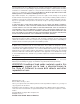
Appendix B: Software Installation Instructions Appendix B Software Installation Instructions B-1 Installing Software Programs After you've installed the operating system, a screen as shown below will appear. You are ready to install software programs and drivers that have not yet been installed. To install these programs, click the icons to the right of these items. Note: To install the Windows OS, please refer to the instructions posted on our Website at http://www.supermicro.com/support/manuals/.
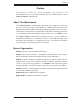
X8QB6-F/X8QBE-F Motherboard User's Manual B-2 Configuring Supero Doctor III The Supero Doctor III program is a web-based management tool that supports remote management capability. It includes Remote and Local Management tools. The local management is called the SD III Client. The Supero Doctor III program included on the CDROM that came with your motherboard allows you to monitor the environment and operations of your system.
Appendix B: Software Installation Instructions Supero Doctor III Interface Display Screen-II (Remote Control) Note: SD III Software Revision 1.0 can be downloaded from our website at: ftp://ftp.Supermicro.com/utility/Supero_Doctor_III/. You can also download SDIII User's Guide at: http://www.supermicro.com/PRODUCT/ Manuals/SDIII/UserGuide.pdf. For Linux, we will still recommend that you use Supero Doctor II.
X8QB6-F/X8QBE-F Motherboard User's Manual Notes B-4
(Disclaimer Continued) The products sold by Supermicro are not intended for and will not be used in life support systems, medical equipment, nuclear facilities or systems, aircraft, aircraft devices, aircraft/emergency communication devices or other critical systems whose failure to perform be reasonably expected to result in significant injury or loss of life or catastrophic property damage.