X8DTU-LN4F+ USER’S MANUAL Revision 1.
The information in this User’s Manual has been carefully reviewed and is believed to be accurate. The vendor assumes no responsibility for any inaccuracies that may be contained in this document, makes no commitment to update or to keep current the information in this manual, or to notify any person or organization of the updates. Please Note: For the most up-to-date version of this manual, please see our website at www.supermicro.com. Super Micro Computer, Inc.
Preface Preface This manual is written for system integrators, PC technicians and knowledgeable PC users. It provides information for the installation and use of the X8DTU-LN4F+ motherboard. About This Motherboard The X8DTU-LN4F+ motherboard supports the Intel 5500/5600 Series processors, the first dual-processing platform that supports the Intel QuickPath Interconnect (QPI) Technology, providing the next generation point-to-point system interface to replace the current Front Side Bus.
X8DTU-LN4F+ Motherboard User’s Manual Conventions Used in the Manual Special attention should be given to the following symbols for proper installation and to prevent damage done to the components or injury to yourself: Danger/Caution: Instructions to be strictly followed to prevent catastrophic system failure or to avoid bodily injury Warning: Important information given to ensure proper system installation or to prevent damage to the components Note: Additional Information given to differentiate various
Contacting Supermicro Contacting Supermicro Headquarters Address: Super Micro Computer, Inc. 980 Rock Ave. San Jose, CA 95131 U.S.A. Tel: +1 (408) 503-8000 Fax: +1 (408) 503-8008 Email: marketing@supermicro.com (General Information) support@supermicro.com (Technical Support) Website: www.supermicro.com Europe Address: Super Micro Computer B.V. Het Sterrenbeeld 28, 5215 ML 's-Hertogenbosch, The Netherlands Tel: +31 (0) 73-6400390 Fax: +31 (0) 73-6416525 Email: sales@supermicro.
X8DTU-LN4F+ Motherboard User’s Manual Table of Contents Preface Chapter 1 Quick Installation Guide 1-1 Installing the CPU ........................................................................................... 1-1 1-2 Installing the CPU Heatsink ............................................................................ 1-1 1-3 Installing the Memory Modules ....................................................................... 1-2 1-4 Installing the I/O Shield (if needed) .....................
Table of Contents Back Panel I/O Port Locations and Definitions ........................................... 3-15 ATX PS/2 Keyboard and PS/2 Mouse Ports ............................................ 3-16 Universal Serial Bus (USB) ...................................................................... 3-17 Serial Ports ............................................................................................... 3-18 Video Connectors ............................................................................
X8DTU-LN4F+ Motherboard User’s Manual GLAN LEDs .............................................................................................. 3-36 IPMI Dedicated LAN LEDs ..................................................................... 3-36 Onboard Power LED ............................................................................... 3-37 BMC Heartbeat LED ............................................................................... 3-37 Rear UID LED ..............................................
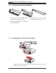
Chapter 1: Quick Installation Guide Chapter 1 Quick Installation Guide 1-1 Installing the CPU A B A. Press the socket clip down to unlock it. Gently lift the socket clip to open the load plate. B. Align the CPU key with the socket key. D C C. Align CPU Pin 1 against Socket Pin 1. Once they are aligned, lower the CPU down to the socket. D. Once the CPU is fully seated on the socket, press the socket clip down to lock it. To avoid damage, do not rub the CPU pins against the socket.
X8DTU-LN4F+ Motherboard User’s Manual 1-3 Installing the Memory Modules A B C A. Align the key on the DIMM module C. Press the notches on the ends of against that of the DIMM socket. the DIMM module inwards to lock it. B. Insert the DIMM module straight down to the DIMM socket. 1-4 Installing the I/O Shield (if needed) A B Note: Chassis and I/O plate images are for illustration only. They may be different from what you have.
Chapter 1: Quick Installation Guide 1-5 Installing the Motherboard A B X8DTU-LN4F+ Rev. 2.0 C 1-6 D Connecting the Power Supply X8DTU-LN4F+ X8DTU-LN4F+ Rev. 2.0 Rev. 2.
X8DTU-LN4F+ Motherboard User’s Manual 1-7 Installing Internal Peripherals Add-on Cards 1-8 Installing External Peripherals Mouse IPMI LAN Keyboard USB 0/1 Serial Port VGA Port (COM1) LAN 1/2 Ports LAN 3/4 Ports UID Switch 1-4
Chapter 2: Overview Chapter 2 Overview 2-1 Overview Checklist Congratulations on purchasing your computer motherboard from an acknowledged leader in the industry. Supermicro boards are designed with the utmost attention to detail to provide you with the highest standards in quality and performance. Please check that the following items have all been included with your motherboard. If anything listed here is damaged or missing, contact your retailer. The following items are included in the retail box.
X8DTU-LN4F+ Motherboard User’s Manual Motherboard Image Note: All graphics shown in this manual were based upon the latest PCB Revision available at the time of publishing of the manual. The motherboard you've received may or may not look exactly the same as the graphics shown in this manual.
KB/MS J1 IPMI_LAN USB2/3 VGA2 P1-DIMM3A P1-DIMM3B P1-DIMM3C P1-DIMM2A P1-DIMM2C P1-DIMM2B P1-DIMM1B P1-DIMM1A P1-DIMM1C P2-DIMM1C P2-DIMM1B P2-DIMM1A P2-DIMM2C JPW1 JPW3 JPW2 FAN1 JPI2C JPK1 FAN7/CPU2 FAN2 JIPMB2 FAN5 IPMB1 FAN4 JOH1 JF1 USB7 FAN6 WOR1 T-SGPIO1 JWF1 2-3 JD1 JPL1 P2-DIMM2A P2-DIMM2B P2-DIMM3B P2-DIMM3C P2-DIMM3A USB6 FAN3 USB4/5 JL1 T-SGPIO2 LE1 FPCTRL PHY JPL2 SXB3: PCI-E 2.0 x8 J3 JWD JTPM JP8 SATA0~5 LAN1 SP1 JBT1 SXB2: PCI-E 2.
X8DTU-LN4F+ Motherboard User’s Manual X8DTU-LN4F+ Quick Reference LAN4 LAN1 LAN2 LAN3 VGA1 COM1 USB0/1 IPMI_LAN J1 VGA2 JD1 PHY JPL1 JPL2 SXB2: PCI-E 2.0 x8+x4 J2 LAN2 USB2/3 UIOP KB/MS LE11 UID LAN1 SP1 JBT1 FAN8/CPU1 P1-DIMM3A P1-DIMM3B P1-DIMM3C P1-DIMM2A P1-DIMM2C P1-DIMM2B SXB3: PCI-E 2.0 x8 J3 P1-DIMM1B P1-DIMM1A P1-DIMM1C SXB1: PCI-E 2.0 x16 CPU1 X8DTU-LN4F+ Rev. 2.
Chapter 2: Overview X8DTU-LN4F+ Jumpers Jumper Description Default Setting JBT1 Clear CMOS See Chapter 3 JI C1/JI C2 SMB to PCI-E Slots Off (Disabled) JPG1 VGA Enable Pins 1~2 (Enabled) JPL1/JPL2 GLAN1/GLAN2 Enable Pins 1-2 (Enabled) JWD Watch Dog Pins 1~2 (Reset) 2 2 X8DTU-LN4F+ Connectors Connectors Description JBT1 Onboard Battery COM1/COM2 COM1/COM2 Serial Connections FAN 1~8 CPU//System Fan Headers (Fans 7, 8: CPU Fans) IPMB1/JIPMB2 4-pin/3-pin External BMC I2C Header (for
X8DTU-LN4F+ Motherboard User’s Manual USB 0/1 Back Panel USB 0/1 USB2/3, 4/5, 6 Front Panel Accessible USB Connections USB 7 Internal USB Connection UID UID (Universal Identifier) Switch UIOP Universal I/O Add-on Card Power (J10) (See the Warning below.
Chapter 2: Overview Motherboard Features CPU • Two Intel® 5500/5600 Series (LGA 1366) processors; each processor supports two full-width Intel QuickPath Interconnect (QPI) links with a total of up to 51.2 GT/s Data Transfer Rate (6.4 GT/s per direction) Memory • 18 240-pin, DDR3 1333/1066/800 MHz SDRAM DIMM sockets in three-channel memory bus. • Support for up to 192 GB* of Registered ECC or 48 GB of Unbuffered ECC/Non-ECC DDR3 memory (*Refer to Supermicro's Memory Recommendation List posted at www.
X8DTU-LN4F+ Motherboard User’s Manual Peripheral Devices BIOS USB Devices • • • • • • Two (2) USB ports on the rear I/O panel (USB 0/1) One (1) USB connection for front access (USB 6) One (1) Internal USB connection (USB 7) Two (2) Type A internal connector (USB 2/3, 4/5) 32 Mb SPI AMI BIOS® SM Flash BIOS APM 1.2, PCI 2.3, ACPI 1.0/2.0/3.0, USB Keyboard, Plug & Play (PnP) and SMBIOS 2.5 Power Config.
Chapter 2: Overview Notes 2-9
QPI Processor#0 Processor#1 C PORT1 PORT1 PORT PORT 7,8,9,10 Gen2 x4 PORT 1,2 Gen2 x8 PORT 3,4 PORT 5,6 F E F QPI QPI Gen2 x16 E DDR3 DIMM B D DDR3 DIMM A DDR3 DIMM DDR3 DIMM DDR3 DIMM B PCI-E x16 C PCI-Ex8 inx4 Slot PCI-E x8 inx16 Slot DDR3 DIMM X8DTU-LN4F+ Motherboard User’s Manual PORT0 IOH 36D CLINK ESI ATMEL AT25DF321 Gen2 x8 (Lane Reversal) SPI CLINK ESI PCIE Port 1-4 Gen1 x4 KAWELA ICH10R Gen1x2 PORT 8,10 PCI COMA USB PCIE Port 5-6 SATA LPC BMC SIO TPM COM
Chapter 2: Overview 2-2 Chipset Overview Built upon the functionality and the capability of the Intel 5520 platform, the X8DTULN4F+ motherboard provides the performance and feature sets required for dualprocessor-based high-end systems and HPC/Cluster servers. The 5520 platform consists of the 5500/5600 Series (LGA 1366) processor, the 36D IOH (IO Hub), and the ICH10R (South Bridge).
X8DTU-LN4F+ Motherboard User’s Manual 2-3 Special Features Recovery from AC Power Loss The Basic I/O System (BIOS) provides a setting for you to determine how the system will respond when AC power is lost and then restored to the system. You can choose for the system to remain powered off (in which case you must press the power switch to turn it back on), or for it to automatically return to a power- on state. See the Advanced BIOS Setup section to change this setting. The default setting is Last State.
Chapter 2: Overview environment or used with Supero Doctor II in Linux. Supero Doctor is used to notify the user of certain system events. For example, you can also configure Supero Doctor to provide you with warnings when the system temperature, CPU temperatures, voltages and fan speeds go beyond a predefined range. 2-5 ACPI Features ACPI stands for Advanced Configuration and Power Interface.
X8DTU-LN4F+ Motherboard User’s Manual 2. To provide adequate power to the add-on cards installed on the motherboard, please connect the UIOP PWR connector to the power supply. It is strongly recommended that you use a high quality power supply that meets ATX power supply Specification 2.02 or above. It must also be SSI compliant. (For more information, please refer to the web site at http://www.ssiforum.org/).
Chapter 3: Installation Chapter 3 Installation 3-1 Static-Sensitive Devices Electrostatic Discharge (ESD) can damage electronic components. To avoid damaging your system board, it is important to handle it very carefully. The following measures are generally sufficient to protect your equipment from ESD. Precautions • Use a grounded wrist strap designed to prevent static discharge. • Touch a grounded metal object before removing the board from the antistatic bag.
X8DTU-LN4F+ Motherboard User's Manual 3-2 Processor and Heatsink Installation When handling the processor package, avoid placing direct pressure on ! the label area of the fan. Notes: 1. Always connect the power cord last, and always remove it before adding, removing or changing any hardware components. Make sure that you install the processor into the CPU socket before you install the CPU heatsink. 2.
Chapter 3: Installation 4. After removing the plastic cap, using your thumb and the index finger, hold the CPU at the north and south center edges. 5. Align the CPU key, the semi-circle cutout, against the socket key, the notch below the gold color dot on the side of the socket. 6. Once both CPU and the socket are aligned, carefully lower the CPU straight down into the socket. (To avoid damaging the CPU or the socket, do not rub the CPU against the surface of the socket or its pins.) 7.
X8DTU-LN4F+ Motherboard User's Manual Installing a Passive CPU Heatsink 1. Do not apply any thermal grease to the heatsink or the CPU die because the required amount has already been applied. 2. Place the heatsink on top of the CPU so that the four mounting holes are aligned with those on the retention mechanism. 3. Install two diagonal screws (e.g. the #1 and the #2 screws) and tighten them until just snug (-do not fully tighten the screws to avoid possible damage to the CPU.) 4.
Chapter 3: Installation Removing the Passive Heatsink Warning: We do not recommend that the CPU or the heatsink be removed. However, if you do need to remove the heatsink, please follow the instructions below to uninstall the heatsink to avoid damaging the CPU or other components. 1. Unplug the power cord from the power supply. 2. Disconnect the heatsink fan wires from the CPU fan header. 3.
X8DTU-LN4F+ Motherboard User's Manual Installing an Active Heatsink 1. Locate the CPU Fan power connector on the motherboard. (Refer to the motherboard layout in Chapter 2 for the CPU Fan location.) 2. Position the heatsink so that the heatsink fan wires are closest to the CPU fan power connector and do not interfere with other components. 3. Inspect the CPU Fan wires to make sure that the wires are routed through the bottom of the heatsink. Fan Wires Heatsink Fins 4.
Chapter 3: Installation 10. Once all four fasteners are securely inserted into the mounting holes, and the heatsink is properly installed on the motherboard, connect the heatsink fan wires to the CPU fan connector. Removing the Active Heatsink Warning: We do not recommend that the CPU or the heatsink be removed. However, if you do need to remove the heatsink, please follow the instructions below to uninstall the heatsink and prevent damage to the CPU or other components. 1.
X8DTU-LN4F+ Motherboard User's Manual 3-3 Installing and Removing the Memory Modules Note: Check Supermicro's website for recommended memory modules. CAUTION Exercise extreme care when installing or removing DIMM modules to prevent any possible damage. Installing & Removing DIMMs 1. Insert the desired number of DIMMs into the memory slots, starting with P1DIMM #1A. (For best performance, please use the memory modules of the same type and same speed in the same bank.) 2.
Chapter 3: Installation Memory Support The X8DTU-LN4F+ Motherboard supports up to 192 GB* Registered ECC or up to 48 GB Unbuffered ECC/Non-ECC DDR3 1333 MHz/1066 MHz/800 MHz in 18 DIMMs. (*Refer to Supermicro's memory recommendation list posted on our website at www.supermicro.com.) Note: Memory Speed support depends on the type(s) of CPU(s) used.
X8DTU-LN4F+ Motherboard User's Manual Memory Support for the Motherboard with the 5500 Processor(s) Installed RDIMM Population for the Motherboard w/5500 Processors Installed DIMM Slots per Channel DIMMs Populated per Channel DIMM Type (Reg.= Registered) Speeds (in MHz) Ranks per DIMM (any combination; SR=Single Rank, DR=Dual Rank, QR=Quad Rank) 3 1 Reg. DDR3 ECC 800,1066,1333 SR or DR 3 1 Reg. DDR3 ECC 800,1066 QR 3 2 Reg. DDR3 ECC 800,1066 Mixing SR, DR 3 2 Reg.
Chapter 3: Installation 1.5V UDIMM Population for the Motherboard w/5600 Processors Installed DIMM Slots per Channel DIMMs Populated per Channel DIMM Type (Unb.= Unbuffered) Speeds (in MHz) Ranks per DIMM (any combination; SR=Single Rank, DR=Dual Rank, QR=Quad Rank) 3 1 Unb. DDR3 ECC/Non-ECC 800,1066,1333 SR or DR 3 2 Unb. DDR3 ECC/Non-ECC 800,1066, 1333 Mixing SR, DR 3 3 Not Available Not Available Not Available Note 1: 1333 MHz for two DIMMs per channel is supported when Unbuf.
X8DTU-LN4F+ Motherboard User's Manual Note 1: Due to OS limitations, some operating systems may not show more than 4 GB of memory. Note 2: Due to memory allocation to system devices, the amount of memory that remains available for operational use will be reduced when 4 GB of RAM is used. The reduction in memory availability is disproportional. (See the following Table.
Chapter 3: Installation 3-4 Motherboard Installation All motherboards have standard mounting holes to fit different types of chassis. Make sure that the locations of all the mounting holes for both motherboard and chassis match. Although a chassis may have both plastic and metal mounting fasteners, metal ones are highly recommended because they ground the motherboard to the chassis. Make sure that the metal standoffs click in or are screwed in tightly.
X8DTU-LN4F+ Motherboard User's Manual Installing the Motherboard 1. Install the I/O shield into the chassis. 2. Locate the mounting holes on the motherboard. 3. Locate the matching mounting holes on the chassis. Align the mounting holes on the motherboard against the mounting holes on the chassis. 4. Install standoffs in the chassis as needed. 5. Install the motherboard into the chassis carefully to avoid damaging motherboard components. 6.
Chapter 3: Installation 3-5 Control Panel Connectors/I/O Ports The I/O ports are color coded in conformance with the PC 99 specification. See the picture below for the colors and locations of the various I/O ports. Back Panel Connectors/I/O Ports 2 5 1 4 6 7 8 X8DTU-LN4F+ Rev. 2.0 3 Back Panel I/O Port Locations and Definitions 1. Keyboard (Purple) 2. PS/2 Mouse (Green) 3. Back Panel USB Port 0 4. Back Panel USB Port 1 5. IPMI_Dedicated LAN 6. COM Port 1 (Turquoise) 7. VGA1 (Blue) 8.
X8DTU-LN4F+ Motherboard User's Manual ATX PS/2 Keyboard and PS/2 PS/2 Keyboard/Mouse Pin Definitions Mouse Ports The ATX PS/2 keyboard and PS/2 PS2 Keyboard PS2 Mouse mouse are located next to the Back Pin# Definition Pin# Definition Panel USB Ports 0~1 on the moth- 1 KB Data 1 Mouse Data erboard. See the table at right for pin definitions.
Chapter 3: Installation Universal Serial Bus (USB) Front Panel USB (USB 0/1) Two Universal Serial Bus ports (USB 0/1) are located on the I/O back panel. Pin# Definition Five USB connections (USB 2/3, 4/5, 1 +5V 6) are located on the motherboard 2 PO- to provide front chassis access. In addition, USB 7, located next to Fan 3 PO+ 4 Ground 6, provides internal USB support.
X8DTU-LN4F+ Motherboard User's Manual Serial Ports Serial COM) Ports Pin Definitions Two COM connections (COM1 & COM2) are located on the motherboard. COM1 is located on the Backplane I/O panel. COM2 is located next to the ICH10R South Bridge to provide additional serial connection support. See the table on the right for pin definitions.
Chapter 3: Installation Ethernet Ports LAN Ports Pin Definition Four Ethernet ports (LAN1/LAN2/ LAN3/LAN4) are located on the I/O backplane. In addition, an IPMI_Dedicated LAN is located on top of the back panel USB ports (USB 0/1) to provide KVM support for IPMI 2.0.
X8DTU-LN4F+ Motherboard User's Manual Front Control Panel JF1 contains header pins for various buttons and indicators that are normally located on a control panel at the front of the chassis. These connectors are designed specifically for use with Supermicro server chassis. See the figure below for the descriptions of the various control panel buttons and LED indicators. Refer to the following section for descriptions and pin definitions. JF1 Header Pins X8DTU-LN4F+ Rev. 2.0 20 19 Ground NMI X X 3.
Chapter 3: Installation Front Control Panel Pin Definitions NMI Button NMI Button Pin Definitions (JF1) The non-maskable interrupt button header is located on pins 19 and 20 of JF1. Refer to the table on the right for pin definitions. Power LED Pin# Definition 19 NMI 20 Ground Power LED Pin Definitions (JF1) The Power LED connection is located on pins 15 and 16 of JF1. Refer to the table on the right for pin definitions. Pin# Definition 15 3.3V 16 FP PWR LED A. NMI B.
X8DTU-LN4F+ Motherboard User's Manual HDD LED HDD LED Pin Definitions (JF1) The HDD LED connection is located on pins 13 and 14 of JF1. Attach a cable here to indicate HDD activity. See the table on the right for pin Pin# Definition 13 ID_UID_SW/3.3VSB 14 HDD Active definitions.
Chapter 3: Installation Overheat (OH)/Fan Fail/PWR Fail/ Blue+ (OH/Fan Fail/PWR Fail/UID LED) Pin Definitions (JF1) UID LED Connect an LED cable to OH/Fan Fail Pin# connection on pins 7 and 8 of JF1 to 7 Red+ (Blue LED Cathode) provide advanced warnings of chassis 8 Blue+ (OH/Fan Fail/PWR Fail/ UID LED) overheat or fan failure. Refer to the table on the right for pin definitions.
X8DTU-LN4F+ Motherboard User's Manual Reset Button Reset Button Pin Definitions (JF1) The Reset Button connection is located on pins 3 and 4 of JF1. Attach it to a hardware reset switch on the computer case. Refer to the table on the right for Pin# Definition 3 Reset 4 Ground pin definitions. Power Button Power Button Pin Definitions (JF1) The Power Button connection is located on pins 1 and 2 of JF1. Momentarily contacting both pins will power on/off the system.
Chapter 3: Installation 3-6 Connecting Cables ATX Power 24-pin Connector Pin Definitions Pin# Definition Pin # Power Connectors 13 +3.3V 1 +3.3V A 24-pin main power supply connector (JPW1) and two 8-pin CPU PWR connectors (JPW2/ 14 -12V 2 +3.3V 15 COM 3 COM JPW3) are located on the motherboard. These 16 PS_ON 4 +5V power connectors meet the SSI EPS 12V 17 COM 5 COM specification.
X8DTU-LN4F+ Motherboard User's Manual Fan Headers Fan Header Pin Definitions This motherboard has six chassis/system fan headers (Fan 1 to Fan6) and two CPU fans (Fan7/Fan8) on the motherboard. All these 4-pin fans headers are backward compatible with the traditional 3-pin fans. However, fan speed control is available Pin# Definition 1 Ground 2 +12V 3 Tachometer 4 PWR Modulation for 4-pin fans only.
Chapter 3: Installation Internal Speaker Internal Buzzer (SP1) Pin Definition The Internal Speaker, located at SP1, can be used to provide audible indica- Pin# tions for various beep codes. See the table on the right for pin definitions. Definitions Pin 1 Pos. (+) Beep In Pin 2 Neg. (-) Alarm Speaker Refer to the layout below for the locations of the Internal Buzzer (SP1).
X8DTU-LN4F+ Motherboard User's Manual DOM Power Connector DOM PWR Pin Definitions A power connector for SATA DOM (Disk_On_Module) Devices is located at JWF1. Connect the appropriate cable here to provide power support for your DOM devices. Pin# Definition 1 +5V 2 Ground 3 Ground Overheat LED/Fan Fail Overheat LED Pin Definitions The JOH1 header is used to connect an LED indicator to provide warnings of chassis overheating or fan failure. This LED will blink when a fan failure occurs.
Chapter 3: Installation T-SGPIO 1/2 Headers T-SGPIO Pin Definitions Two SGPIO (Serial-Link General Purpose Input/Output) headers are Pin# located on the motherboard. These headers support Serial_Link interfaces for onboard SATA connections. See the table on the right for pin Definition Pin Definition 1 NC 2 NC 3 Ground 4 Data 5 Load 6 Ground 7 CLK 8 No Connection definitions.
X8DTU-LN4F+ Motherboard User's Manual UIO Power Connector Universal I/O Power Header Pin Definitions A Universal I/O (UIO) Power connector is located next to the UID switch. Pins# Definition Pin # Connect this connector to the power B1 +5V A1 +3.3V supply to provide adequate power to B2 +5V A2 +3.3V the UIO device installed on the slot for B3 +5V A3 +3.3V this device to function properly. See the layout below for the location. B4 +5V A4 +3.3V B5 +5V A5 +3.3V B6 +5V A6 +3.
Chapter 3: Installation Unit Identification Switch/LED UID Switch (UID) Pin Definitions A Unit Identifier switch (UID) and a rear UID LED indicator (LE11) are located next to LAN Pin# Definition ports on the back of the chassis. When the user pushes the rear UID switch, the rear UID LED (LE11) will be turned on. Push the UID switch again to turn off the LED indicator.
X8DTU-LN4F+ Motherboard User's Manual Trusted Platform Module Header Trusted Platform Module (TPM) Header Pin Definitions A Trusted Platform Module (TPM) header (JTPM) is located next to the COM2 connection. This header provides TPM support to ensure data integrity and system security. Refer to the table on the right for pin definitions. Pin# Definition Definition 1 LPC Clock 2 GND 3 LPC FRAME# 4 Key 5 LPC Reset# 6 +5V (X) 7 LAD3 8 LAD2 9 +3.
Chapter 3: Installation 3-7 Jumper Settings Explanation of Jumpers Connector Pins 3 2 1 3 2 1 To modify the operation of the motherboard, jumpers can be used to choose between optional settings. Jumpers create shorts between two pins to change the function of the connector. Jumper Cap Pin 1 is identified with a square solder pad Setting on the printed circuit board. See the motherboard layout pages for jumper locations.
X8DTU-LN4F+ Motherboard User's Manual CMOS Clear JBT1 is used to clear CMOS. Instead of pins, this "jumper" consists of contact pads to prevent the accidental clearing of CMOS. To clear CMOS, use a metal object such as a small screwdriver to touch both pads at the same time to short the connection. Always remove the AC power cord from the system before clearing CMOS. Note 1. For an ATX power supply, you must completely shut down the system, remove the AC power cord and then short JBT1 to clear CMOS.
Chapter 3: Installation I2C Bus to PCI-Exp. Slots I2C for PCI/PCI-E slots Jumper Settings Jumpers JI2C1 and JI2C2 allow you to Jumper Setting connect the System Management Bus (I2C) to PCI and PCI-Express slots. These two jumpers are to be set at the Definition Closed Enabled Open Disabled (Default) same time. The default setting is Open to disable the connections. See the table on the right for jumper settings.
X8DTU-LN4F+ Motherboard User's Manual 3-8 Onboard LED Indicators Activity LED Link LED GLAN LEDs Four LAN ports (LAN 1/LAN 2/LAN3/LAN4) are located on the I/O Backplane of the Rear View (when facing the rear side of the chassis) LAN 1/2 Activity LED (Right) LED State motherboard. Each Ethernet LAN port has two LEDs. The Green LED indicates activ- Color Status Definition ity, while the other Link LED may be green, amber or off to indicate the speed of the Green Flashing Active connections.
Chapter 3: Installation Onboard Power LED Onboard PWR LED (LE1) State An Onboard Power LED is located at LE1 on the motherboard. When this LED is lit, State/Color Off System Off (PWR cable not connected) Green System Power On the system is on. Be sure to turn off the system and unplug the power cord before Definition removing or installing components. See the tables at right for more information.
X8DTU-LN4F+ Motherboard User's Manual Rear UID LED UID LED (LE11) Status The rear UID LED is located at LE11 on the backplane. This LED is used in Color/State OS Status conjunction with the rear UID switch to provide easy identification of a system Blue: On Windows OS Unit Identified Blue: Blinking Linux OS Unit Identified that might be in need of service. Refer to UID Switch on Page 3-31 for more information.
Chapter 3: Installation 3-9 Serial ATA Connections Serial ATA Ports Serial ATA Pin Definitions There are six Serial ATA Ports (ISATA0~I-SATA 5) located on the Pin# Definition motherboard. These por ts, sup- 1 Ground ported by the Intel ICH10R South 2 TX_P Bridge, provide serial-link signal connections, which are faster than the 3 TX_N 4 Ground connections of Parallel ATA. See the 5 RX_N table on the right for pin definitions.
X8DTU-LN4F+ Motherboard User's Manual Notes 3-40
Chapter 4: Troubleshooting Chapter 4 Troubleshooting 4-1 Troubleshooting Procedures Use the following procedures to troubleshoot your system. If you have followed all of the procedures below and still need assistance, refer to the ‘Technical Support Procedures’ and/or ‘Returning Merchandise for Service’ section(s) in this chapter. Note: Always disconnect the power cord before adding, changing or installing any hardware components. Before Power On 1.
X8DTU-LN4F+ Motherboard User's Manual No Video 1. If the power is on but you have no video, remove all the add-on cards and cables. 2. Use the speaker to determine if any beep codes exist. Refer to the Appendix for details on beep codes. System Boot Failure If the system does not display POST or does not respond after the power is turned on, check the following: 1. Check for any error beep from the motherboard speaker. • If there is no error beep, try to turn on the system without DIMM modules.
Chapter 4: Troubleshooting Memory Errors When a No_Memory_Beep_Code is issued by the system, check the following: 1. Make sure that the memory modules are compatible and that the DIMM modules are properly and fully installed. (For memory compatibility, refer to the Memory Compatibility Chart posted on our website @ http://www.supermicro. com.) 2. Check if different speeds of DIMMs have been installed. It is strongly recommended to use the same RAM speed for all DIMMs in the system. 3.
X8DTU-LN4F+ Motherboard User's Manual tings in the BIOS to make sure that the CPU and System temperatures are within normal range. Also check the front panel Overheat LED and make sure that the Overheat LED is not on. 5. Adequate power supply: Make sure that the power supply provides adequate power to the system. Make sure that all power connectors are connected. Please refer to our website for more information on minimum power requirement. 6.
Chapter 4: Troubleshooting services. They should know of any possible problem(s) with the specific system configuration that was sold to you. 1. Please go through the ‘Troubleshooting Procedures’ and 'Frequently Asked Question' (FAQ) sections in this chapter or see the FAQs on our web site (http://www.supermicro.com/support/faqs/) before contacting Technical Support. 2. BIOS upgrades can be downloaded from our website (http://www.supermicro. com/support/bios/). 3.
X8DTU-LN4F+ Motherboard User's Manual your motherboard model and download the BIOS file to your computer. Also, check the current BIOS revision and make sure that it is newer than your BIOS before downloading. You can choose from the zip file and the .exe file. If you choose the zip BIOS file, please unzip the BIOS file onto a bootable USB device. Run the batch file using the format AMI.bat filename.rom from your bootable USB device to flash the BIOS. Then, your system will automatically reboot.
Chapter 5: AMI BIOS Chapter 5 BIOS 5-1 Introduction This chapter describes the AMI BIOS Setup Utility for the X8DTU-LN4F+. The AMI ROM BIOS is stored in a Flash EEPROM and can be easily updated. This chapter describes the basic navigation of the AMI BIOS Setup Utility setup screens. Starting BIOS Setup Utility To enter the AMI BIOS Setup Utility screens, press the key while the system is booting up. Note: In most cases, the key is used to invoke the AMI BIOS setup screen.
X8DTU-LN4F+ Motherboard User’s Manual Starting the Setup Utility Normally, the only visible Power-On Self-Test (POST) routine is the memory test. As the memory is being tested, press the key to enter the main menu of the AMI BIOS Setup Utility. From the main menu, you can access the other setup screens. An AMI BIOS identification string is displayed at the left bottom corner of the screen below the copyright message. Warning! Do not upgrade the BIOS unless your system has a BIOS-related issue.
Chapter 5: AMI BIOS System Overview: The following BIOS information will be displayed: System Time/System Date Use this option to change the system time and date. Highlight System Time or System Date using the arrow keys. Key in new values through the keyboard and press . Press the key to move between fields. The date must be entered in Day MM/DD/YY format. The time is entered in HH:MM:SS format. (Note: The time is in the 24-hour format. For example, 5:30 P.M. appears as 17:30:00.
X8DTU-LN4F+ Motherboard User’s Manual 5-3 Advanced Setup Configurations Use the arrow keys to select Boot Setup and hit to access the submenu items: Boot Features Quick Boot If enabled, this feature will skip certain tests during POST to reduce the time needed for system boot. The options are Enabled and Disabled. Quiet Boot This option allows the bootup screen options to be modified between POST messages or the OEM logo. Select Disabled to display the POST messages.
Chapter 5: AMI BIOS Hit 'Del' Message Display This feature displays "Press DEL to run Setup" during POST. The options are Enabled and Disabled. Interrupt 19 Capture Interrupt 19 is the software interrupt that handles the boot disk function. When this item is set to Enabled, the ROM BIOS of the host adaptors will "capture" Interrupt 19 at boot and allow the drives that are attached to these host adaptors to function as bootable disks.
X8DTU-LN4F+ Motherboard User’s Manual Clock Spread Spectrum Select Enable to use the feature of Clock Spectrum, which will allow the BIOS to monitor and attempt to reduce the level of Electromagnetic Interference caused by the components whenever needed. The options are Disabled and Enabled.
Chapter 5: AMI BIOS Simultaneous Multi-Threading (Available when supported by the CPU) Set to Enabled to use the Simultaneous Multi-Threading Technology, which will result in increased CPU performance. The options are Disabled and Enabled. Active Processor Cores Set to Enabled to use a processor's Second Core and beyond. (Please refer to Intel's web site for more information.) The options are All, 1 and 2.
X8DTU-LN4F+ Motherboard User’s Manual Advanced Chipset Control The items included in the Advanced Settings submenu are listed below: CPU Bridge Configuration This feature allows the user to configure CPU Bridge settings. The items included in the submenu are listed below. • CPU Revision: This item displays the CPU revision number. • Current QPI Frequency: This item displays the current QPI frequency. • • • • Current CPU 1 Memory Frequency: This item displays the current CPU 1 memory frequency.
Chapter 5: AMI BIOS Memory Mode The options are Independent, Channel Mirror, and Lockstep. Independent - All DIMMs are available to the operating system. Channel Mirror - The motherboard maintains two identical copies of all data in memory for redundancy. Lockstep - The motherboard uses two areas of memory to run the same set of operations in parallel.
X8DTU-LN4F+ Motherboard User’s Manual Intel I/OAT The Intel I/OAT (I/O Acceleration Technology) significantly reduces CPU overhead by leveraging CPU architectural improvements, freeing resources for more other tasks. The options are Disabled and Enabled. DCA Technology (Available when Intel I/OAT is enabled) Select Enabled to use Intel's DCA (Direct Cache Access) Technology to enhance data transfer efficiency. The options are Enabled and Disabled.
Chapter 5: AMI BIOS USB Functions This feature allows the user to decide the number of onboard USB ports to be enabled. The Options are: Disabled, 2 USB ports, 4 USB ports, 6 USB ports, 8 Ports, 10 Ports and 12 USB ports. USB 2.0 Controller (Available when the item: USB Functions is disabled) This item indicates if the onboard USB 2.0 controller is activated. The default setting is Enabled. Legacy USB Support Select Enabled to use Legacy USB devices.
X8DTU-LN4F+ Motherboard User’s Manual ICH AHCI Codebase (Available when the option-AHCI is selected.) Use this feature to select the AHCI Codebase for the ICH South Bridge. The options are BIOS Native Module and Intel AHCI ROM. SATA#2 Configuration (Available when the option-IDE is selected.) Selecting Enhanced will set SATA#2 to native SATA mode. The options are Disabled, and Enhanced.
Chapter 5: AMI BIOS Select Auto to allow the AMI BIOS to automatically detect the PIO mode. Use this value if the IDE disk drive support cannot be determined. Select 0 to allow the AMI BIOS to use PIO mode 0. It has a data transfer rate of 3.3 MB/s. Select 1 to allow the AMI BIOS to use PIO mode 1. It has a data transfer rate of 5.2 MB/s. Select 2 to allow the AMI BIOS to use PIO mode 2. It has a data transfer rate of 8.3 MB/s. Select 3 to allow the AMI BIOS to use PIO mode 3.
X8DTU-LN4F+ Motherboard User’s Manual Select UDMA2 to allow the BIOS to use Ultra DMA mode 2. It has a data transfer rate of 33.3 MB/s. Select UDMA3 to allow the BIOS to use Ultra DMA mode 3. It has a data transfer rate of 44.4 MB/s. Select UDMA4 to allow the BIOS to use Ultra DMA mode 4. It has a data transfer rate of 66.6 MB/s. S.M.A.R.T. For Hard disk drives Self-Monitoring Analysis and Reporting Technology (SMART) can help predict impending drive failures.
Chapter 5: AMI BIOS SXB1 PCI-E 2.0 x16/x8 Option ROM/SXB3 PCI-E 2.0 x8 Option ROM/SXB2 PCI-E 2.0 x8/x4 Option ROM/SXB2 PCI-E 2.0 x4 Option ROM Select Enabled to enable PCI-E slots indicated above. It can also enable Option ROMs specified to boot computer using a network interface from these slots. The options are Enabled and Disabled. Onboard LAN Option ROM Select Select iSCSI to use iSCSI Option ROMs to boot the computing using a network device.
X8DTU-LN4F+ Motherboard User’s Manual Serial Port Number This feature allows the user decide which serial port to be used for Console Redirection. The options are COM 1 and COM 2. Base Address, IRQ This item displays the based address and IRQ of the serial port specified above. Serial Port Mode This feature allows the user to set the serial port mode for Console Redirection. The options are 115200 8, n 1; 57600 8, n, 1; 38400 8, n, 1; 19200 8, n, 1; and 9600 8, n, 1.
Chapter 5: AMI BIOS CPU Overheat Alarm This option allows the user to select the CPU Overheat Alarm setting which determines when the CPU OH alarm will be activated to provide warning of possible CPU overheat. Warning! 1.Any temperature that exceeds the CPU threshold temperature predefined by the CPU manufacturer may result in CPU overheat or system instability. When the CPU temperature reaches this predefined threshold, the CPU and system cooling fans will run at full speed. 2.
X8DTU-LN4F+ Motherboard User’s Manual seeing a temperature reading (i.e., 25oC). The CPU Temperature feature will display the CPU temperature status as detected by the BIOS: Low – This level is considered as the ‘normal’ operating state. The CPU temperature is well below the CPU ‘Temperature Tolerance’. The motherboard fans and CPU will run normally as configured in the BIOS (Fan Speed Control). User intervention: No action required. Medium – The processor is running warmer.
Chapter 5: AMI BIOS Select "Balanced/BL" for the onboard fans to run at a speed that will balance the needs between system cooling and power saving. The BL setting is recommended for regular systems with normal hardware configurations. Select "Energy Saving/ES" for best power efficiency and maximum quietness. The Options are: Full Speed/FS, Performance/PF, Balanced/BL, and Energy Saving/ES. Voltage Monitoring CPU1 Vcore, CPU2 Vcore, CPU1 DIMM, CPU2 DIMM, 1.1V, 3.3V, 1.5V, 5V, 12V, 3.3VSB, 5VSB, and Vbat.
X8DTU-LN4F+ Motherboard User’s Manual NUMA Support Select Enabled to use the feature of Non-Uniform Memory Access to improve CPU performance. The options are Disabled, Enabled and NUMA for SLES 11. WHEA Support Select Enabled to enable Windows Hardware Error Architecture (WHEA) support which will provide a common infrastructure for the system to handle hardware errors on Windows platforms in order to reduce system crashes due to hardware errors and to enhance system recovery and health monitoring.
Chapter 5: AMI BIOS TPM Owner Status This item displays the status of TPM Ownership. IPMI Configuration Intelligent Platform Management Interface (IPMI) is a set of common interfaces that IT administrators can use to monitor system health and to manage the system as a whole. For more information on the IPMI specifications, please visit Intel's website at www.intel.com. IPMI Firmware Version This item displays the current IPMI Firmware Version.
X8DTU-LN4F+ Motherboard User’s Manual • Event Data. Clear BMC System Event Log Clear BMC System Log now Select OK and press the key to clear the BMC system log immediately. Select Cancel to keep the BMC System log. The options are OK and Cancel. Caution: Any cleared information is unrecoverable. Make absolutely sure that you no longer need any data stored in the log before clearing the BMC Event Log.
Chapter 5: AMI BIOS Gateway Address (When IP Address Source is set to 'Static') The BIOS will automatically enter the Gateway address of this machine; however it may be overwritten. The value of each three-digit number separated by dots should not exceed 255. Mac Address (When IP Address Source is set to 'Static') The BIOS will automatically enter the Mac address of this machine; however it may be over-ridden.
X8DTU-LN4F+ Motherboard User’s Manual 5-4 Security Settings The AMI BIOS provides a Supervisor and a User password. If you use both passwords, the Supervisor password must be set first. Supervisor Password This item indicates if a Supervisor password has been entered for the system. "Not Installed" means a Supervisor password has not been used. User Password This item indicates if a user password has been entered for the system. "Not Installed" means that a user password has not been used.
Chapter 5: AMI BIOS Clear User Password (Available only when User Password has been set) This item allows you to clear a user password after it has been entered. Password Check Select Setup for the system to check for a password at Setup. Select Always for the system to check for a password at bootup. The options are Setup and Always.
X8DTU-LN4F+ Motherboard User’s Manual • 1st Drive - [RAID: XXXXXXXXX] Retry Boot Devices Select Enabled to enable Retry Boot Devices support to allow the system to attempt to boot from a specific boot device after a boot failure. The options are Enabled and Disabled. 5-6 Exit Options Select the Exit tab from the AMI BIOS Setup Utility screen to enter the Exit BIOS Setup screen.
Chapter 5: AMI BIOS Load Optimal Defaults To set this feature, select Load Optimal Defaults from the Exit menu and press . Then, select OK to allow the AMI BIOS to automatically load Optimal Defaults to the BIOS Settings. The Optimal settings are designed for maximum system performance, but may not work best for all computer applications. Load Fail-Safe Defaults To set this feature, select Load Fail-Safe Defaults from the Exit menu and press .
X8DTU-LN4F+ Motherboard User’s Manual Notes 5-28
Appendix A: BIOS POST Error Codes Appendix A BIOS Error Beep Codes During the POST (Power-On Self-Test) routines, which are performed each time the system is powered on, errors may occur. Non-fatal errors are those which, in most cases, allow the system to continue the boot-up process. The error messages normally appear on the screen. Fatal errors will not allow the system to continue the boot-up procedure. If a fatal error occurs, you should consult with your system manufacturer for possible repairs.
X8DTU-LN4F+ Motherboard User's Manual Notes A-2
Appendix B: Software Installation Instructions Appendix B Software Installation Instructions B-1 Installing Software Programs After you've installed the operating system, a screen as shown below will appear. You are ready to install software programs and drivers that have not yet been installed. To install these programs, click the icons to the right of these items. Note: To install the Windows OS, please refer to the instructions posted on our website at http://www.supermicro.com/support/manuals/.
X8DTU-LN4F+ Motherboard User's Manual B-2 Configuring Supero Doctor III The Supero Doctor III program is a web-based management tool that supports remote management capability. It includes Remote and Local Management tools. The local management is called the SD III Client. The Supero Doctor III program included on the CDROM that came with your motherboard allows you to monitor the environment and operations of your system.
Appendix B: Software Installation Instructions Supero Doctor III Interface Display Screen-II (Remote Control) Note: SD III Software Revision 1.0 can be downloaded from our Web site at: ftp://ftp.supermicro.com/utility/Supero_Doctor_III/. You can also download SDIII User's Guide at: http://www.supermicro.com/PRODUCT/ Manuals/SDIII/UserGuide.pdf. For Linux, we will still recommend that you use Supero Doctor II.
X8DTU-LN4F+ Motherboard User's Manual Notes B-4
(Disclaimer Continued) The products sold by Supermicro are not intended for and will not be used in life support systems, medical equipment, nuclear facilities or systems, aircraft, aircraft devices, aircraft/emergency communication devices or other critical systems whose failure to perform be reasonably expected to result in significant injury or loss of life or catastrophic property damage.