
User`s manual
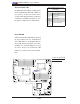


2-32
X8DTU/X8DTU-F User's Manual
KB /MS
Fan8
(CPU1Fan)
IPMI LAN
USB 0/1
COM1
PHY
VGA
LAN1
LAN2
LAN CTRL
BMC CTRL
BIOS
COM2
USB6
USB7
USB4/5
JTAG Of CPLD
JPI2C
P1-DIMM3A
P1-DIMM3B
P1-DIMM2A
P1-DIMM2B
P1-DIMM1A
P1-DIMM1B
P2-DIMM1B
P2-DIMM1A
P2-DIMM2B
P2-DIMM2A
P2-DIMM3B
P2-DIMM3A
LE2
JUIDB
JPL1
J10
UIOP
SXB2: PCI-E 2.0 x 8
SXB1: PCI-E 2.0 x 16
SXB3: PCI-E 2.0 x 8 in x 4 Slot
J1
J2
J3
JPG1
Fan6
IPMB
JI2C1
JBT1
J13
J14
J12
Fan5
JL1
USB2/3 JLPC1
CPU2
CPU1
Intel I5520
North Bridge
Intel ICH10R
South Bridge
T-SGPIO2
T-SGPIO1
J17
JWD
JF1
JOH1
LE1
Fan4
Fan3
SP1
Buzzer
JBAT1
Battery
Fan2
Fan1
JPW1
JPW3
JPW2
JD1
I-SATA5
I-SATA4
I-SATA3
I-SATA2
I-SATA1
I-SATA0
X8DTU/-F
Fan7(CPU2 Fan)
FP CTRL
CPLD
PWRLED/SPK
Rev. 2.0
A
B
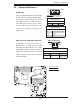
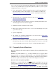
A. Onboard Power LED
B. Rear UID LED
Onboard Power LED
An Onboard Power LED is located at LE1
on the motherboard. When this LED is on,
the system is on. Be sure to turn off the
system and unplug the power cord before
removing or installing components. See
the tables at right for more information.
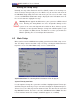
Onboard PWR LED Indicator (LE1)
LED Settings
LED Color Defi nition
Off System Off (PWR cable
not connected)
Green System On
Green:
Flashing
Quickly
ACPI S1 State
Green:
Flashing
Slowly
ACPI S3 (STR) State
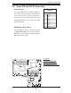
Rear UID LED
A Rear Unit Identifi er LED (LE2) is located
on the backpanel on the motherboard.
This LED works in conjunction with the
Rear UID Switch to provide easy iden-
tifi cation of a unit that might be in need
of service. Please refer to the Rear UID
Switch in Section 2-4 for more informa-
tion.