X8DTU X8DTU-F USER’S MANUAL Revision 1.
The information in this User’s Manual has been carefully reviewed and is believed to be accurate. The vendor assumes no responsibility for any inaccuracies that may be contained in this document, makes no commitment to update or to keep current the information in this manual, or to notify any person or organization of the updates. Please Note: For the most up-to-date version of this manual, please see our web site at www.supermicro.com. Super Micro Computer, Inc.
Preface Preface About This Manual This manual is written for system integrators, PC technicians and knowledgeable PC users. It provides information for the installation and use of the X8DTU/ X8DTU-F motherboard. About This Motherboard The X8DTU/X8DTU-F supports the Intel 5500/5600 Series processors, the first dual-processing platform that supports the Intel QuickPath Interconnect (QPI) Technology, providing the next generation point-to-point system interface to replace the current Front Side Bus.
X8DTU/X8DTU-F User's Manual Contacting Supermicro Headquarters Address: Super Micro Computer, Inc. 980 Rock Ave. San Jose, CA 95131 U.S.A. Tel: +1 (408) 503-8000 Fax: +1 (408) 503-8008 Email: marketing@supermicro.com (General Information) support@supermicro.com (Technical Support) Web Site: www.supermicro.com Europe Address: Super Micro Computer B.V. Het Sterrenbeeld 28, 5215 ML 's-Hertogenbosch, The Netherlands Tel: +31 (0) 73-6400390 Fax: +31 (0) 73-6416525 Email: sales@supermicro.
Preface Notes v
X8DTU/X8DTU-F User's Manual Table of Contents Preface Chapter 1 Introduction 1-1 Overview ........................................................................................................ 1-1 Checklist .......................................................................................................... 1-1 X8DTU/X8DTU-F Quick Reference ................................................................ 1-5 Motherboard Features ......................................................................
Table of Contents Unit Identifier Switches............................................................................. 2-17 3. Front Control Panel ................................................................................... 2-18 4. Front Control Panel Pin Definitions .......................................................... 2-19 NMI Button ............................................................................................... 2-19 Power LED .................................................
X8DTU/X8DTU-F User's Manual Before Power On ............................................................................................ 3-1 No Power ........................................................................................................ 3-1 No Video ......................................................................................................... 3-1 Losing the System’s Setup Configuration ....................................................... 3-2 Memory Errors ...................
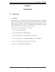
Chapter 1: Introduction Chapter 1 Introduction 1-1 Overview Checklist Congratulations on purchasing your computer motherboard from an acknowledged leader in the industry. Supermicro boards are designed with the utmost attention to detail to provide you with the highest standards in quality and performance. Check that the following items have all been included with your motherboard. If anything listed here is damaged or missing, contact your retailer. The following items are included in the retail box.
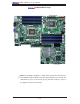
X8DTU/X8DTU-F User's Manual X8DTU/X8DTU-F Image Note: The drawings and pictures shown in this manual were based on the latest PCB Revision available at the time of publishing of the manual. The motherboard you’ve received may or may not look exactly the same as the graphics shown in the manual.
Chapter 1: Introduction JPW3 Fan8 (CPU1Fan) KB /MS P1-DIMM3A JPW1 P1-DIMM3B IPMI LAN P1-DIMM2A USB 0/1 JPW2 X8DTU/X8DTU-F Motherboard Layout P1-DIMM2B JPI2C P1-DIMM1A PHY CPU2 COM1 P1-DIMM1B Fan1 Fan2 VGA Battery X8DTU/-F LAN1 Fan7(CPU2 Fan) CPU1 JBAT1 Rev. 2.0 Buzzer SP1 Fan3 P2-DIMM1B LAN2 P2-DIMM1A JUIDB P2-DIMM3A J3 I-SATA5 I-SATA4 I-SATA3 SXB1: PCI-E 2.0 x 16 I-SATA2 I-SATA0 J2 J10 I-SATA1 J1 SXB2: PCI-E 2.0 x 8 SXB3: PCI-E 2.
X8DTU/X8DTU-F User's Manual JPW3 Fan8 (CPU1Fan) KB /MS P1-DIMM3A JPW1 P1-DIMM3B IPMI LAN P1-DIMM2A USB 0/1 JPW2 X8DTU/X8DTU-F Quick Reference P1-DIMM2B JPI2C P1-DIMM1A PHY CPU2 COM1 P1-DIMM1B Fan1 Fan2 VGA Battery X8DTU/-F LAN1 Fan7(CPU2 Fan) CPU1 JBAT1 Rev. 2.0 Buzzer SP1 Fan3 P2-DIMM1B LAN2 P2-DIMM1A JUIDB P2-DIMM3A J3 I-SATA5 I-SATA4 I-SATA3 SXB1: PCI-E 2.0 x 16 I-SATA2 I-SATA0 J2 J10 I-SATA1 J1 SXB2: PCI-E 2.0 x 8 SXB3: PCI-E 2.
Chapter 1: Introduction X8DTU/X8DTU-F Quick Reference Jumper Description Default Setting JBT1 CMOS Clear (See Chapter 2) JI2C1/JI2C2 SMB to PCI-Exp.
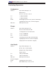
X8DTU/X8DTU-F User's Manual Motherboard Features CPU • Two Intel® 5500/5600 Series (LGA 1366) processors; each processor supports two full-width Intel QuickPath Interconnect (QPI) links with a total of up to 51.2 GT/s Data Transfer Rate (6.4 GT/s per direction) Memory • Twelve 240-pin DIMM sockets support up to 192 GB* of DDR3 Registered ECC or up to 48 GB of Unbuffered ECC/Non-ECC DDR3 1333 MHz/1066 MHz/800 MHz in 12 DIMM modules.
Chapter 1: Introduction • • Chassis intrusion detection System resource alert via Supero Doctor III ACPI Features • • • • Slow blinking LED for suspend state indicator Main switch override mechanism ACPI Power Management Keyboard Wakeup from Soft-off Onboard I/O • Intel ICH10R supports six SATA ports (with support of RAID0, RAID1, RAID10, RAID5 in the Windows OS Environment, and RAID 0, RAID 1, RAID 10 for the Linux OS) • Intel 82576 dual-channel Gigabit Ethernet controller supports dual Giga-bit
E C F QPI E F DDR3 DIMM PROCESSOR#1 DDR3 DIMM B PROCESSOR#0 D DDR3 DIMM DDR3 DIMM PCI-E x8 PCI-E X16 B QPI A QPI Port1 Port0 Gen2 x4 Intel 82576 Ports Ports1,2 7,8,9,10 (Lane Reversal) Intel 5520 RJ45RJ45 Gen2 x16 Gen2 x8 PCI-E x8 in x4 Slot C DDR3 DIMM DDR3 DIMM X8DTU/X8DTU-F User's Manual Ports5,6 Ports3,4 ESI CLINK SST 25VF016 Gen2 x8 SPI (Lane Reversal) ESI CLINK PCIE Ports 1-6 Ports Intel ICH10R 8,10 USB PCI COMA SATA BMC COMB VGA RJ45 SATA SATA SATA SATA SATA SATA
Chapter 1: Introduction 1-2 Chipset Overview Built upon the functionality and the capability of the Intel 5520 platform, the X8DTU/X8DTU-F motherboard provides the performance and feature set required for dual-processor-based high-end systems with configuration optimized for HPC/ Cluster servers and intensive applications. The 5520 platform consists of the 5500/5600 Series (LGA 1366) processor, the 5520 (IO Hub), and the ICH10R (South Bridge).
X8DTU/X8DTU-F User's Manual 1-3 Special Features Recovery from AC Power Loss BIOS provides a setting for you to determine how the system will respond when AC power is lost and then restored to the system. You can choose for the system to remain powered off (in which case you must press the power switch to turn it back on) or for it to automatically return to a power- on state. See the Advanced BIOS Setup section to change this setting. The default setting is Last State.
Chapter 1: Introduction notify the user of certain system events. For example, you can also configure Supero Doctor to provide you with warnings when the system temperature, CPU temperatures, voltages and fan speeds go beyond a pre-defined range. 1-5 ACPI Features ACPI stands for Advanced Configuration and Power Interface.
X8DTU/X8DTU-F User's Manual installed on the motherboard, please connect the UIOP PWR connector to the power supply. It is strongly recommended that you use a high quality power supply that meets ATX power supply Specification 2.02 or above. It must also be SSI compliant (For more information, please refer to the web site at http://www.ssiforum.org/). Additionally, in areas where noisy power transmission is present, you may choose to install a line filter to shield the computer from noise.
Chapter 2: Installation Chapter 2 Installation 2-1 Static-Sensitive Devices Electrostatic Discharge (ESD) can damage electronic components. To prevent damage to your system board, it is important to handle it very carefully. The following measures are generally sufficient to protect your equipment from ESD. Precautions • Use a grounded wrist strap designed to prevent static discharge. • Touch a grounded metal object before removing the board from the antistatic bag.
X8DTU/X8DTU-F User's Manual 2-2 Motherboard Installation All motherboards have standard mounting holes to fit different types of chassis. Make sure that the locations of all the mounting holes for both motherboard and chassis match. Although a chassis may have both plastic and metal mounting fasteners, metal ones are highly recommended because they ground the motherboard to the chassis. Make sure that the metal standoffs click in or are screwed in tightly.
Chapter 2: Installation 2-3 Processor and Heatsink Installation When handling the processor package, avoid placing direct pressure on ! the label area of the fan. Notes: 1. Always connect the power cord last and always remove it before adding, removing or changing any hardware components. Make sure that you install the processor into the CPU socket before you install the CPU heatsink. 2. Make sure to install the motherboard into the chassis before you install the CPU heatsink and heatsink fans. 3.
X8DTU/X8DTU-F User's Manual CPU Socket CPU 1. After removing the plastic cap, using your thumb and the index finger, hold the CPU at the north and south center edges. 2. Align the CPU key, the semicircle cutout, against the socket key, the notch below the gold Socket Keys color dot on the side of the socket. 3. Once both the CPU and the socket are aligned, carefully lower the CPU straight down into the socket.
Chapter 2: Installation Installing a CPU Heatsink 1. Do not apply any thermal grease to the heatsink or the CPU die because the required amount has already been applied. Screw#1 Screw#2 2. Place the heatsink on top of the CPU so that the four mounting holes are aligned with those on the retention mechanism. Screw#1 Install Screw#1 3. Install two diagonal screws (ie the #1 and the #2 screws) and tighten them until just snug (-do not fully tighten the screws to avoid possible damage to the CPU.) 4.
X8DTU/X8DTU-F User's Manual Removing the Heatsink Warning: We do not recommend that the CPU or the heatsink be removed. However, if you do need to remove the heatsink, please follow the instructions below to uninstall the heatsink and prevent damage to the CPU or other components. 1. Unplug the power cord from the power supply. 2. Disconnect the heatsink fan wires from the CPU fan header. 3.
Chapter 2: Installation 2-4 Memory Installation Note: Check the Supermicro web site for recommended memory modules. CAUTION Exercise extreme care when installing or removing DIMM modules to prevent any possible damage. Also note that the memory is interleaved to improve performance. DIMM Installation 1. Insert the desired number of DIMMs into the memory slots, starting with P1-DIMM 1A.
X8DTU/X8DTU-F User's Manual Memory Support The X8DTU/X8DTU-F supports up to 192 GB* Registered ECC or up to 48 GB of Unbuffered ECC/Non-ECC DDR3 1333 MHz/1066 MHz/800 MHz in 12 DIMMs. (Refer to our website at www.supermicro.com for the recommended memory list. Memory Support for the Motherboard with the 5500 Processor(s) Installed RDIMM Population for the Motherboard w/5500 Processors Installed DIMM Slots per Channel DIMMs Populated per Channel DIMM Type (Reg.
Chapter 2: Installation 1.5V UDIMM Population for the Motherboard w/5600 Processors Installed DIMM Slots per Channel DIMMs Populated per Channel DIMM Type (Unb.= Unbuffered) Speeds (in MHz) Ranks per DIMM (any combination; SR=Single Rank, DR=Dual Rank, QR=Quad Rank) 3 1 Unb. DDR3 ECC/Non-ECC 800,1066,1333 SR or DR 3 2 Unb. DDR3 ECC/Non-ECC 800,1066, 1333 Mixing SR, DR Note 1: 1333 MHz for two DIMMs per channel is supported when Unbuf./ECC DIMMs are used. Note 2: MIxing of 1.35V and 1.
X8DTU/X8DTU-F User's Manual Possible System Memory Allocation & Availability System Device Size Physical Memory Remaining (-Available) (4 GB Total System Memory) Firmware Hub flash memory (System BIOS) 1 MB 3.99 GB Local APIC 4 KB 3.99 GB Area Reserved for the chipset 2 MB 3.99 GB I/O APIC (4 Kbytes) 4 KB 3.99 GB PCI Enumeration Area 1 256 MB 3.76 GB PCI Express (256 MB) 256 MB 3.51 GB PCI Enumeration Area 2 (if needed) -Aligned on 256-MB boundary- 512 MB 3.
Chapter 2: Installation 2-5 Control Panel Connectors/IO Ports The I/O ports are color coded in conformance with the PC 99 specification. See the picture below for the colors and locations of the various I/O ports. 1. Back Panel Connectors/IO Ports 2 5 1 4 3 X8DTU/-F Rev. 2.0 6 7 Back Panel I/O Port Locations and Definitions Back Panel Connectors 1. Keyboard (Purple) 2. PS/2 Mouse (Green) 3. Back Panel USB Port 0 4. Back Panel USB Port 1 5. IPMI_Dedicated LAN (X8DTU-F) 6.
X8DTU/X8DTU-F User's Manual 2. Back Panel IO & USB Pin Definitions ATX PS/2 Keyboard and PS/2 Mouse Ports PS/2 Keyboard/Mouse Pin Definitions The ATX PS/2 keyboard and PS/2 PS2 Keyboard PS2 Mouse are located next to the Backpanel Pin# Pin# USB ports 0/1 on the motherboard. 1 KB Data 1 Mouse Data See the table at right for pin definitions.
Chapter 2: Installation Universal Serial Bus (USB) Back Panel USB (USB 0/1) There are eight USB 2.0 (Universal Serial Bus) connections on the Pin# Definitions Pin# Definition 1 Vcc 2 Data- 3 Data+ 4 Ground 5 NA 1 +5V motherboard. Backpanel USB Ports 2 PO- 0/1 are located next to Keyboard/ 3 PO+ 4 Ground 5 N/A Mouse Connectors.
X8DTU/X8DTU-F User's Manual Gigabit LAN (Ethernet) Ports Two Gigabit Ethernet ports (LAN1/2) are located next to the VGA port on GLAN Ports Pin Definition Pin# Definition the IO backplane. Additionally, an 9 P2V5SB 18 SGND IPMI_Dedicated_LAN with full KVM 10 TD0+ 19 Act LED support is located above the USB Ports 1/2 on the X8DTU-F.
Chapter 2: Installation Serial Ports Serial Ports-COM1 Pin Definitions Two COM connections (COM1 & COM2) are located on the moth- Pin # erboard. COM1 is located next to 1 DCD 6 DSR the Video port on the Backplane IO 2 RXD 7 RTS panel. COM2 (JCOM2) is located next to the BMC Controller to provide 3 TXD 8 CTS 4 DTR 9 RI 5 Ground 10 N/A front accessible serial connection.
X8DTU/X8DTU-F User's Manual VGA Connector A VGA connector is located next to COM Port1 on the IO backplane. This connector provides video and CRT display. Refer to the board layout below for the location. VGA/CRT Pin Definitions Pin# Definition Pin# Definition 1 Red 10 Ground 2 Green 11 MS0 3 Blue 12 MS1: SDA (DDC Data) 4 MS2 13 HSYNC 5 Ground 14 VSYSNC 6 Ground 15 MS3: SCL (DDC CLK) 7 Ground 16 Case 8 Ground 17 Case 9 NC NC= No Connection 1. VGA X8DTU/-F Rev. 2.
Chapter 2: Installation Unit Identifier Switches UID Switch Two Unit Identifier (UID) Switches and two LED Indicators are located on the mother- Pin# Definition 1 Ground board. The Rear UID Switch (JUID) is located 2 Ground next to LAN 2 port on the backplane. The 3 Button In Front Panel UID Switch is located at Pin 13 of the Front Control Panel. Connect a cable 4 Ground to Pins 13/14 of JF1 for Front Panel UID UID LED (LED 2) Status Switch support.
X8DTU/X8DTU-F User's Manual 3. Front Control Panel JF1 contains header pins for various buttons and indicators that are normally located on a control panel at the front of the chassis. These connectors are designed specifically for use with Supermicro server chassis. See the figure below for the descriptions of the various control panel buttons and LED indicators. Refer to the following section for descriptions and pin definitions. JF1 Header Pins 20 19 Ground NMI X8DTU/-F Rev. 2.
Chapter 2: Installation 4. Front Control Panel Pin Definitions NMI Button NMI Button Pin Definitions (JF1) The non-maskable interrupt button header is located on pins 19 and 20 of JF1. Refer to the table on the right for pin definitions. Pin# Definition 19 Control 20 Ground Power LED The Power LED connection is located on pins 15 and 16 of JF1. Refer to the table on the right for pin definitions. Power LED Pin Definitions (JF1) Pin# Definition 15 +5V 16 Ground A. NMI B.
X8DTU/X8DTU-F User's Manual HDD LED/UID Switch HDD LED/UID Switch Pin Definitions (JF1) The HDD/UID LED connection is located on pins 13 and 14 of JF1. Attach a hard drive LED cable here to display disk activity status (for any hard drive Pin# Definition 13 UID Switch/3,3V 14 HDD Active activities on the system, including Serial ATA activities). Connect a UID switch cable to use UID switch connection. The front UID switch works in conjunction with UID LED located at Pins 7/8.
Chapter 2: Installation Overheat (OH)/Fan Fail/PWR Fail/ UID LED OH/Fan Fail/ PWR Fail/Blue_UID LED Pin Definitions (JF1) Connect an LED cable to pins 7 and Pin# Definition 8 of JF1 to use the Overheat/Fan 7 Blue_LED Cathode (UID) Fail/Power Fail and UID LED connections. The Red LED on pin 7 provides 8 OH/Fan Fail/PWR Fail/UID LED OH/Fan Fail/PWR Fail LED Status warnings of an overheat, fan failure or Pin 7 Pin 8 power failure.
X8DTU/X8DTU-F User's Manual Reset Button Reset Button Pin Definitions (JF1) The Reset Button connection is located on pins 3 and 4 of JF1. Attach it to a hardware reset switch on the computer case. Refer to the table on the right for Pin# Definition 3 Reset 4 Ground pin definitions. Power Button Pin Definitions (JF1) Power Button The Power Button connection is located on pins 1 and 2 of JF1. Momentarily contacting both pins will power on/off the system.
Chapter 2: Installation 2-6 Connecting Cables 20-pin Main Power Connector Pin Definitions ATX Power Connector Pin# There are a 20-pin main power supply connector(JPW1) and two 8-pin CPU PWR connectors (JPW2/JPW3) on the motherboard. These power connectors meet the SSI EPS 12V specification. Processor Power Connector Definition 1 +3.3Vdc Orange 11 +3.3Vdc Orange 2 +3.
X8DTU/X8DTU-F User's Manual UIO Riser_Card Power Connector Universal IO PWR Connector Pin Definitions In addition to the Primary 20-pin power connector and the 8-pin CPU Pin# Definition B1 P5V A1 P3V3 PWR connectors, the Universal IO B2 P5V A2 P3V3 Power Connector (UIOP) located at B3 P5V A3 P3V3 J10 is also required for the riser cards installed on the motherboard. This B4 P5V A4 P3V3 B5 P5V A5 P3V3 power connector is used to provide B6 P5V A6 P3V3 power to the riser card.
Chapter 2: Installation Fan Headers Fan Header Pin Definitions The X8DTU/X8DTU-F has six chassis/system fan headers (Fan1 to Fan6) and two CPU fans Pin# Definition (Fan7/Fan8) on the motherboard. All these 1 Ground 4-pin fans headers are backward compatible 2 +12V 3 Tachometer 4 PWR Modulation with the traditional 3-pin fans. However, fan speed control is available for 4-pin fans only. The fan speeds are controlled by a Hardware Monitoring setting in the BIOS.
X8DTU/X8DTU-F User's Manual T-SGPIO Headers T-SGPIO Pin Definitions Two SGPIO (Serial-Link General Purpose Input/Output) headers (T- Pin# Definition Pin Definition SGPIO-1/T-SGPIO-2) are located at 1 NC 2 NC below the front panel control connec- 3 Ground 4 Data tor (JF1) on the motherboard. These headers support serial link interfaces 5 Load 6 Ground 7 Clock 8 NC for the onboard SATA connectors. See Note: NC= No Connections the table on the right for pin definitions.
Chapter 2: Installation Power SMB (I2C) Connector PWR SMB Pin Definitions Power System Management Bus (I2C) Connector (JPI 2C) monitors power supply, fan and system temperatures. See the table on the right for pin definitions. Pin# Definition 1 Clock 2 Data 3 PWR Fail 4 Ground 5 +3.3V SMB Header Pin Definitions IPMB I2C SMB (X8DTU-F) A System Management Bus header for the IPMI slot is located at IPMB.
X8DTU/X8DTU-F User's Manual 2-7 Jumper Settings Explanation of Jumpers Connector Pins 3 2 1 3 2 1 To modify the operation of the motherboard, jumpers can be used to choose between optional settings. Jumpers create shorts between two pins to change Jumper Cap the function of the connector. Pin 1 is identified with a square solder pad Setting on the printed circuit board. See the motherboard layout pages for jumper locations.
Chapter 2: Installation CMOS Clear JBT1 is used to clear CMOS. Instead of pins, this "jumper" consists of contact pads to prevent the accidental clearing of CMOS. To clear CMOS, use a metal object such as a small screwdriver to touch both pads at the same time to short the connection. Always remove the AC power cord from the system before clearing CMOS. Note: For an ATX power supply, you must completely shut down the system, remove the AC power cord and then short JBT1 to clear CMOS.
X8DTU/X8DTU-F User's Manual I2C Bus to PCI-Exp. Slots I2C to PCI-Exp Jumper Settings Jumpers JI2C1 and JI2C2 allow you to connect the System Management Bus (I2C) to PCI-Express slots. The default setting is Open to disable the connec- Jumper Definition Closed Enabled Open Disabled (Default) tion. See the table on the right for jumper settings. VGA Enable VGA Enable/Disable Jumper Settings (JPG1) JPG1 allows you to enable or disable the onboard VGA connection.
Chapter 2: Installation 2-8 Onboard Indicators GLAN LEDs Link Activity LED LED Rear View (when facing the rear side of the chassis) There are two GLAN ports (LAN1/LAN2) on the motherboard. Each Gigabit Ether- GLAN Activity Indicator LED Settings (Right) net LAN port has two LEDs.
X8DTU/X8DTU-F User's Manual Onboard Power LED Onboard PWR LED Indicator (LE1) LED Settings An Onboard Power LED is located at LE1 on the motherboard. When this LED is on, LED Color Definition Off System Off (PWR cable not connected) system and unplug the power cord before Green System On removing or installing components. See the tables at right for more information. Green: Flashing Quickly ACPI S1 State Green: Flashing Slowly ACPI S3 (STR) State the system is on.
Chapter 2: Installation 2-9 Serial ATA and PCI-E Connections Serial ATA Pin Definitions Serial ATA Ports Six Serial ATA Ports (I-SATA0~I-SATA 5) are located at JS1~JS6 on the motherboard. These ports provide serial-link signal transmission, which is faster than that of the traditional Parallel ATA. See the table on the right for pin definitions. PCI-Express Gen. 2 Slots Pin# Definition 1 Ground 2 TX_P 3 TX_N 4 Ground 5 RX_N 6 RX_P 7 Ground Three PCI-Express (Gen.
X8DTU/X8DTU-F User's Manual Notes 2-34
Chapter 3: Troubleshooting Chapter 3 Troubleshooting 3-1 Troubleshooting Procedures Use the following procedures to troubleshoot your system. If you have followed all of the procedures below and still need assistance, refer to the ‘Technical Support Procedures’ and/or ‘Returning Merchandise for Service’ section(s) in this chapter. Note: Always disconnect the power cord before adding, changing or installing any hardware components. Before Power On 1.
X8DTU/X8DTU-F User's Manual 2. Use the speaker to determine if any beep codes exist. Refer to the Appendix for details on beep codes. Losing the System’s Setup Configuration 1. Make sure that you are using a high quality power supply. A poor quality power supply may cause the system to lose the CMOS setup information. Refer to Section 1-5 for details on recommended power supplies. 2. The battery on your motherboard may be old. Check to verify that it still supplies ~3VDC.
Chapter 3: Troubleshooting users, so it is best to first check with your distributor or reseller for troubleshooting services. They should know of any possible problem(s) with the specific system configuration that was sold to you. 1. Please go through the ‘Troubleshooting Procedures’ and 'Frequently Asked Question' (FAQ) sections in this chapter or see the FAQs on our Web site (http://www.supermicro.com/support/faqs/) before contacting Technical Support. 2.
X8DTU/X8DTU-F User's Manual site. Select your motherboard model and download the BIOS file to your computer. Also, check the current BIOS revision and make sure that it is newer than your BIOS before downloading. You can choose from the zip file and the .exe file. If you choose the zip BIOS file, please unzip the BIOS file onto a bootable USB device. Run the batch file using the format flash.bat filename.rom from your a bootable USB device to flash the BIOS. Then, your system will automatically reboot.
Chapter 4: AMI BIOS Chapter 4 BIOS 4-1 Introduction This chapter describes the AMI BIOS Setup Utility for the X8DTU/X8DTU-F. The AMI ROM BIOS is stored in a Flash EEPROM and can be easily updated. This chapter describes the basic navigation of the AMI BIOS Setup Utility setup screens. Starting BIOS Setup Utility To enter the AMI BIOS Setup Utility screens, press the key while the system is booting up. Note: In most cases, the key is used to invoke the AMI BIOS setup screen.
X8DTU/X8DTU-F User’s Manual Starting the Setup Utility Normally, the only visible Power-On Self-Test (POST) routine is the memory test. As the memory is being tested, press the key to enter the main menu of the AMI BIOS Setup Utility. From the main menu, you can access the other setup screens. An AMI BIOS identification string is displayed at the left bottom corner of the screen below the copyright message. Warning! Do not upgrade the BIOS unless your system has a BIOS-related issue.
Chapter 4: AMI BIOS AMI BIOS • Version: This item displays the BIOS revision used in your system. • Build Date: This item displays the date when this BIOS was complete. Processor The AMI BIOS will automatically display the status of the processor used in your system: • CPU Type: This item displays the type of CPU used in the motherboard. • Speed: This item displays the speed of the CPU detected by the BIOS.
X8DTU/X8DTU-F User’s Manual 4-3 Advanced Setup Configurations Use the arrow keys to select Boot Setup and hit to access the submenu items: Boot Features Quick Boot If Enabled, this option will skip certain tests during POST to reduce the time needed for system boot. The options are Enabled and Disabled. Quiet Boot This option allows the bootup screen options to be modified between POST messages or the OEM logo. Select Disabled to display the POST messages.
Chapter 4: AMI BIOS Wait For 'F1' If Error This forces the system to wait until the 'F1' key is pressed if an error occurs. The options are Disabled and Enabled. Hit 'Del' Message Display This feature displays "Press DEL to run Setup" during POST. The options are Enabled and Disabled. Watch Dog Function If enabled, the Watch Dog Timer will allow the system to reboot when it is inactive for more than 5 minutes. The options are Enabled and Disabled.
X8DTU/X8DTU-F User’s Manual Hardware Prefetcher (Available when supported by the CPU) If set to Enabled, the hardware pre fetcher will pre fetch streams of data and instructions from the main memory to the L2 cache in the forward or backward manner to improve CPU performance. The options are Disabled and Enabled. Adjacent Cache Line Prefetch (Available when supported by the CPU) The CPU fetches the cache line for 64 bytes if this option is set to Disabled.
Chapter 4: AMI BIOS C1E Support Select Enabled to use the feature of Enhanced Halt State. C1E significantly reduces the CPU's power consumption by reducing the CPU's clock cycle and voltage during a "Halt State." The options are Disabled and Enabled. Intel® C-STATE Tech If enabled, C-State is set by the system automatically to either C2, C3 or C4 state. The options are Disabled and Enabled.
X8DTU/X8DTU-F User’s Manual QPI Links Speed This feature selects QPI's data transfer speed. The options are Slow-mode, and Full Speed. QPI Frequency This selects the desired QPI frequency. The options are Auto, 4.800 GT, 5.866GT, 6.400 GT. QPI L0s and L1 This enables the QPI power state to low power. L0s and L1 are automatically selected by the motherboard. The options are Disabled and Enabled. Memory Frequency This feature forces a DDR3 to run a frequency other than what the system has detected.
Chapter 4: AMI BIOS Hysteresis Temperature (This feature is available when Closed Loop is enabled.) Temperature Hysteresis is the temperature lag (in degrees Celsius) after the set DIMM temperature threshold is reached before Closed Loop Throttling begins. The options are Disabled, 1.5oC, 3.0oC, and 6.0oC. Guardband Temperature (This feature is available when Closed Loop is enabled.) This is the temperature which applies to the DIMM temperature threshold. Each step is in 0.5oC increment.
X8DTU/X8DTU-F User’s Manual providing the user with greater reliability, security and availability in networking and data-sharing. The options are Enabled and Disabled. SR-IOV Supported Select Enabled to enable Single Root I/O Virtualization (SR-IOV) support which works in conjunction with the Intel Virtualization Technology and allow multiple operating systems running simultaneously within a single computer via natively share PCI-Express devices in order to enhance network connectivity and performance.
Chapter 4: AMI BIOS USB Functions This feature allows the user to decide the number of onboard USB ports to be enabled. The Options are: Disabled, 2 USB ports, 4 USB ports, 6 USB ports, 8 Ports, 10 Ports and 12 USB ports. USB 2.0 Controller This item indicates if the onboard USB 2.0 controller is activated. The default setting is Enabled. Legacy USB Support Select Enabled to use Legacy USB devices.
X8DTU/X8DTU-F User’s Manual SATA AHCI (Available when the option-AHCI is selected.) Select Enable to enable the function of Serial ATA Advanced Host Interface. (Take caution when using this function. This feature is for advanced programmers only.) IDE Detect Timeout (sec) Use this feature to set the time-out value for the BIOS to detect the ATA, ATAPI devices installed in the system. The options are 0 (sec), 5, 10, 15, 20, 25, 30, and 35.
Chapter 4: AMI BIOS PCI-E Slot from SXB1/PCI-E Slot from SXB2/PCI-E Slot from SXB3 Select Enabled to enable PCI-E SXB1 slot, PCI-E SXB2 slot or PCI-E SXB3 slot. It can also enable Option ROMs to boot computer using a network interface from these slots. (SXB1, a x16 slot, can be configured into two x8 slots. SXB2, a x8 slot, can be configured into two x4 slots.) The options are Enabled and Disabled.
X8DTU/X8DTU-F User’s Manual Serial Port Mode This feature allows the user to set the serial port mode for Console Redirection. The options are 115200 8, n 1; 57600 8, n, 1; 38400 8, n, 1; 19200 8, n, 1; and 9600 8, n, 1. Flow Control This feature allows the user to set the flow control for Console Redirection. The options are None, Hardware, and Software. Redirection After BIOS POST Select Disabled to turn off Console Redirection after Power-On Self-Test (POST).
Chapter 4: AMI BIOS The options are: • The Early Alarm: Select this setting if you want the CPU overheat alarm (including the LED and the buzzer) to be triggered as soon as the CPU temperature reaches the CPU overheat threshold as predefined by the CPU manufacturer.
X8DTU/X8DTU-F User’s Manual User intervention: No action is required. However, consider checking the CPU fans and the chassis ventilation for blockage. High – The processor is running hot. This is a ‘caution’ level since the CPU’s ‘Temperature Tolerance’ has been reached (or has been exceeded) and may activate an overheat alarm.
Chapter 4: AMI BIOS High Performance Event Timer Select Enabled to activate the High Performance Event Timer (HPET) that produces periodic interrupts at a much higher frequency than a Real-time Clock (RTC) does in synchronizing multimedia streams, providing smooth playback and reducing the dependency on other timestamp calculation devices, such as an x86 RDTSC Instruction embedded in the CPU. The High Performance Event Timer is used to replace the 8254 Programmable Interval Timer.
X8DTU/X8DTU-F User’s Manual Status of BMC Working The Baseboard Management Controller (BMC) manages the interface between system management software and platform hardware. This item displays the status of the current BMC controller. View BMC System Event Log This feature displays the BMC System Event Log (SEL). It shows the total number of entries of BMC System Events. To view an event, select an Entry Number and pressing to display the information as shown in the screen.
Chapter 4: AMI BIOS Set LAN Configuration Set this feature to configure the IPMI LAN adapter with a network address as shown in the following graphics. Channel Number - Enter the channel number for the SET LAN Config command. This is initially set to [1]. Press "+" or "-" on your keyboard to change the Channel Number. Channel Number Status - This feature returns the channel status for the Channel Number selected above: "Channel Number is OK" or "Wrong Channel Number".
X8DTU/X8DTU-F User’s Manual SET PEF Configuration PEF Support Select Enabled to enable the function of Platform Event Filter (PEF) which will interpret BMC events and perform actions based on pre-determined settings or 'traps' under IPMI 1.5 specifications. Powering the system down or sending an alert when a triggering event is detected. The default is Disabled. The following will appear if PEF Support is set to Enabled.
Chapter 4: AMI BIOS BMC Watch Dog TimeOut [Min:Sec] This option appears if BMC Watch Dog Timer Action (above) is enabled. This is a timed delay in minutes or seconds, before a system power down or reset after an operating system failure is detected. The options are [5 Min], [1 Min], [30 Sec], and [10 Sec]. DMI Event Log Configuration View Event Log Use this option to view the System Event Log. Mark All Events as Read This option marks all events as read. The options are OK and Cancel.
X8DTU/X8DTU-F User’s Manual Supervisor Password This item indicates if a Supervisor password has been entered for the system. "Not Installed" means a Supervisor password has not been used. User Password This item indicates if a user password has been entered for the system. "Not Installed" means that a user password has not been used. Change Supervisor Password Select this feature and press to access the submenu, and then type in a new Supervisor Password.
Chapter 4: AMI BIOS 4-5 Boot Configuration Use this feature to configure boot settings. Boot Device Priority This feature allows the user to specify the sequence of priority for the Boot Device. The settings are 1st boot device, 2nd boot device, 3rd boot device, 4th boot device, 5th boot device and Disabled. • 1st Boot Device - [USB: XXXXXXXXX] • 2nd Boot Device - [CD/DVD: XXXXXXXXX] Hard Disk Drives This feature allows the user to specify the boot sequence from all available hard disk drives.
X8DTU/X8DTU-F User’s Manual 4-6 Exit Options Select the Exit tab from the AMI BIOS Setup Utility screen to enter the Exit BIOS Setup screen. Save Changes and Exit When you have completed the system configuration changes, select this option to leave the BIOS Setup Utility and reboot the computer, so the new system configuration parameters can take effect. Select Save Changes and Exit from the Exit menu and press .
Appendix A: BIOS POST Error Codes Appendix A BIOS Error Beep Codes During the POST (Power-On Self-Test) routines, which are performed each time the system is powered on, errors may occur. Non-fatal errors are those which, in most cases, allow the system to continue the boot-up process. The error messages normally appear on the screen. Fatal errors will not allow the system to continue the boot-up procedure. If a fatal error occurs, you should consult with your system manufacturer for possible repairs.
X8DTU/X8DTU-F User's Manual Notes A-2
Appendix B: Software Installation Instructions Appendix B Software Installation Instructions B-1 Installing Software Programs After you've installed the Windows Operating System, a screen as shown below will appear. You are ready to install software programs and drivers that have not yet been installed. To install these software programs and drivers, click the icons to the right of these items. (Note: To install the Windows OS, please refer to the Windows OS Installation Guide posted at http://www.
X8DTU/X8DTU-F User's Manual B-2 Configuring Supero Doctor III The Supero Doctor III program is a Web-based management tool that supports remote management capability. It includes Remote and Local Management tools. The local management is called the SD III Client. The Supero Doctor III program included on the CDROM that came with your motherboard allows you to monitor the environment and operations of your system.
Appendix B: Software Installation Instructions Supero Doctor III Interface Display Screen-II (Remote Control) Note: SD III Software Revision 1.0 can be downloaded from our Web site at: ftp://ftp.supermicro.com/utility/Supero_Doctor_III/. You can also download SDIII User's Guide at: http://www.supermicro.com/PRODUCT/ Manuals/SDIII/UserGuide.pdf. For Linux, we will still recommend that you use Supero Doctor II.
X8DTU/X8DTU-F User's Manual Notes B-4
(Disclaimer Continued) The products sold by Supermicro are not intended for and will not be used in life support systems, medical equipment, nuclear facilities or systems, aircraft, aircraft devices, aircraft/emergency communication devices or other critical systems whose failure to perform be reasonably expected to result in significant injury or loss of life or catastrophic property damage.