
User`s manual


2-10
X7SB4/X7SBE User's Manual
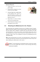
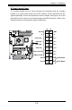
Power LED
The Power LED connection is located on
pins 15 and 16 of JF1. Refer to the table
ontherightforpindenitions.
NMI Button
The non -maskable interrupt button
header is located on pins 19 and 20 of
JF1. Refer to the table on the right for
pindenitions.
NMI Button
Pin Denitions (JF1)
Pin#Denition
19 Control
20 Ground
Power LED
Pin Denitions (JF1)
Pin#Denition
15 +5V
16 Ground
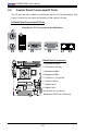
C. Front Control Panel Pin Denitions
A. NMI
B. Power LED
Power Button
OH/Fan Fail LED
1
NIC1 LED
Reset Button
2
HDD LED
Power LED
Reset
PWR
Vcc
Vcc
Vcc
Vcc
Ground
Ground
1920
Vcc
X
Ground
NMI
X
Vcc
PWR Fail LED
NIC2 LED
B
A
X7SB4