
User`s manual


2-26
X7DWT/X7DWT-INF User's Manual
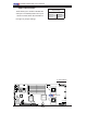
JPL1
J_VMEM
JL1
LE2
LE1
JBT1
LAN1
LAN2
BIOS
SIMSO IPMI
LAN
CTRL
Battery
LE3
J4
VGA
CTRL
SMB
JPL2
SGPIO
CPLD
Intel
5400
North Bridge
CPU 2
FP CTRL
JWD
CPU 1
FAN1/2
20-Pin PWR
PWSMB
CTRL
InfiniBand
DIMM2B
DIMM2A
DIMM1B
DIMM1A
20-Pin PWR
4-Pin Aux. PWR
S I/O
JPG1
JWOL
Intel ESB2
South Bridge
FAN3/4
JSPK
COM1
SATA2
DIMM4B
FPUSB2/3
BANK4
USB0/1
DIMM4A
DIMM3B
DIMM3A
BANK3
BANK2BANK1
VGA
SATA3
SATA0
SATA1
PCI-Express x16
FAN5/6
FAN7/8
Infini- Band
X7DWT-INF
B
A. LE2 (IB Link LED)
B. LE3 (IB Activity LED)
Infi niBand Link LED (LE2)
Settings
Color Status Defi nition
Green Solid Infi niBand
Connected
Off Off No connection
Infi niBand LED Indicators (LE2/
LE3)
Two Infi niBand LED Indicators (LE2/LE3)
are located on the motherboard. The
green LED (LE2) is the Infi niBand Link
LED; while the yellow LED (LE3) indicates
activity. Refer to the table on the right for
details. Also see the layout below for the
LED locations.
Infi niBand Activity LED (LE3)
Settings
Color Status Defi nition
Yellow Solid Infi niBand:
Active
Yellow Dim Infi niBand:
Connected,
Activity: Idle
Off Off No connection
A