
User`s manual


2-24
X7DWT/X7DWT-INF User's Manual
JPL1
J_VMEM
JL1
LE2
LE1
JBT1
LAN1
LAN2
BIOS
SIMSO IPMI
LAN
CTRL
Battery
LE3
J4
VGA
CTRL
SMB
JPL2
SGPIO
CPLD
Intel
5400
North Bridge
CPU 2
FP CTRL
JWD
CPU 1
FAN1/2
20-Pin PWR
PWSMB
CTRL
InfiniBand
DIMM2B
DIMM2A
DIMM1B
DIMM1A
20-Pin PWR
4-Pin Aux. PWR
S I/O
JPG1
JWOL
Intel ESB2
South Bridge
FAN3/4
JSPK
COM1
SATA2
DIMM4B
FPUSB2/3
BANK4
USB0/1
DIMM4A
DIMM3B
DIMM3A
BANK3
BANK2BANK1
VGA
SATA3
SATA0
SATA1
PCI-Express x16
FAN5/6
FAN7/8
Infini- Band
X7DWT-INF
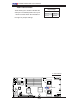
VGA Enable/Disable
Jumper Settings
Both Jumpers Defi nition
Pins 1-2 Enabled
Pins 2-3 Disabled
A
A. VGA Enabled
VGA Enable/Disable
JPG1 allows you to enable or disable the
VGA port. The default position is on pins
1 and 2 to enable VGA. See the table on
the right for jumper settings.