
User`s manual


Chapter 2: Installation
2-23
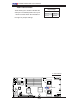
JPL1
J_VMEM
JL1
LE2
LE1
JBT1
LAN1
LAN2
BIOS
SIMSO IPMI
LAN
CTRL
Battery
LE3
J4
VGA
CTRL
SMB
JPL2
SGPIO
CPLD
Intel
5400
North Bridge
CPU 2
FP CTRL
JWD
CPU 1
FAN1/2
20-Pin PWR
PWSMB
CTRL
InfiniBand
DIMM2B
DIMM2A
DIMM1B
DIMM1A
20-Pin PWR
4-Pin Aux. PWR
S I/O
JPG1
JWOL
Intel ESB2
South Bridge
FAN3/4
JSPK
COM1
SATA2
DIMM4B
FPUSB2/3
BANK4
USB0/1
DIMM4A
DIMM3B
DIMM3A
BANK3
BANK2BANK1
VGA
SATA3
SATA0
SATA1
PCI-Express x16
FAN5/6
FAN7/8
Infini- Band
X7DWT-INF
CMOS Clear
JBT1 is used to clear CMOS. Instead of pins, this "jumper" consists of contact
pads to prevent the accidental clearing of CMOS. To clear CMOS, use a metal
object such as a small screwdriver to touch both pads at the same time to short the
connection. Always remove the AC power cord from the system before clearing
CMOS. Note: You must completely shut down the system, remove the AC power
cord and then short JBT1 to clear CMOS.
A
B
A. Clear CMOS
B. Watch Dog Enable
Watch Dog Enable/Disable
Watch Dog is a system monitor that can reboot
the system when a software application hangs.
Close pins 1-2 to reset the system if an applica-
tion hangs. Close pins 2-3 to generate a non-
maskable interrupt signal for the application that
hangs. See the table on the right for jumper set-
tings. Watch Dog must also be enabled in the
BIOS.
Watch Dog
Jumper Settings (JWD)
Jumper Setting Defi nition
Pins 1-2 Reset
(default)
Pins 2-3 NMI
Open Disabled