
User`s manual


2-22
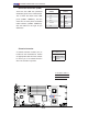
X7DWT/X7DWT-INF User's Manual
JPL1
J_VMEM
JL1
LE2
LE1
JBT1
LAN1
LAN2
BIOS
SIMSO IPMI
LAN
CTRL
Battery
LE3
J4
VGA
CTRL
SMB
JPL2
SGPIO
CPLD
Intel
5400
North Bridge
CPU 2
FP CTRL
JWD
CPU 1
FAN1/2
20-Pin PWR
PWSMB
CTRL
InfiniBand
DIMM2B
DIMM2A
DIMM1B
DIMM1A
20-Pin PWR
4-Pin Aux. PWR
S I/O
JPG1
JWOL
Intel ESB2
South Bridge
FAN3/4
JSPK
COM1
SATA2
DIMM4B
FPUSB2/3
BANK4
USB0/1
DIMM4A
DIMM3B
DIMM3A
BANK3
BANK2BANK1
VGA
SATA3
SATA0
SATA1
PCI-Express x16
FAN5/6
FAN7/8
Infini- Band
X7DWT-INF
2-6 Jumper Settings
Explanation of
Jumpers
To modify the operation of the
motherboard, jumpers can be used
to choose between optional settings.
Jumpers create shorts between two
pins to change the function of the
connector. Pin 1 is identifi ed with a
square solder pad on the printed circuit
board. See the motherboard layout
pages for jumper locations.
Note: On two pin jumpers, "Closed"
means the jumper is on and "Open"
means the jumper is off the pins.
Connector
Pins
Jumper
Cap
Setting
Pin 1-2 short
3 2 1
3 2 1
GLAN Enable/Disable
JPL1/JPL2 enable or disable GLAN
Port1/GLAN Port2 on the mother-
board. See the table on the right for
jumper settings. The default setting
is Enabled.
A
A. GLAN Port1 Enable
B. GLAN Port2 Enable
B
GLAN Enable
Jumper Settings
Pin# Defi nition
Open Enabled (default)
2-3 Disabled